illrrrrrrW
illrrrrrrW - Free and Open Source Software
illrrrrrrW - Free and Open Source Software
- No tags were found...
You also want an ePaper? Increase the reach of your titles
YUMPU automatically turns print PDFs into web optimized ePapers that Google loves.
V2A<br />
1/ 2 12AX7<br />
V,<br />
60.<br />
.0 ' l MEG .0'<br />
2 V,<br />
to<br />
6AF6<br />
.EG<br />
INPUT<br />
MEG<br />
470K<br />
"1,<br />
' MEG<br />
.0'<br />
to<br />
'~<br />
MEG 8<br />
'.0 MEG<br />
7<br />
51-D.p.t,'<br />
V2. • SWITCH<br />
MODE<br />
1/2 12AX7 POS ITIO N<br />
2 WIOE'"<br />
SHIFT<br />
, NARROW SHIFT<br />
S'"<br />
,<br />
200<br />
mM<br />
c<br />
200<br />
mM<br />
c<br />
200<br />
mM<br />
c<br />
200<br />
mM<br />
c<br />
200<br />
mM<br />
c<br />
I~O "'"<br />
212~ '"<br />
GE<br />
12K<br />
125V<br />
15 mA<br />
IN540<br />
.. ~ pF<br />
200V<br />
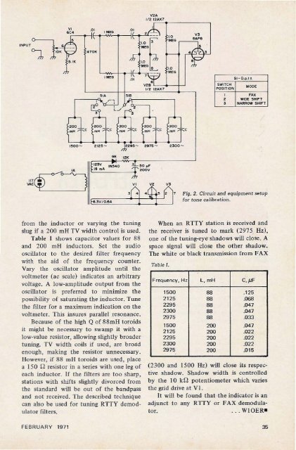
Fig. 2. Circuit and equipment setup<br />
fo r tone calibration .<br />
from the induct or or varying the tuning<br />
slug if a 200 mH TV width control is used.<br />
Table I shows capacitor values fo r 88<br />
and 200 mH indu ctors. Set the aud io<br />
oscillator to the desired filter frequency<br />
with th e aid of th e frequency coun ter.<br />
Vary th e oscillator amplitude until the<br />
voltmeter (ac scale) indic ates an arb itrary<br />
voltage. A low -am plitude out put from the<br />
oscillator is preferre d to minimize the<br />
po ssibility of saturating the inductor. Tune<br />
the filt er for a maximum indication on the<br />
voltmeter. This insures parallel resonance.<br />
Because of the high Q of 88 m H toroid s<br />
it might be necessary to swamp it with a<br />
low-value resistor, allow ing slightly bro ader<br />
tu ning. TV width coils if used, are broad<br />
enough, making the resistor unnecessary.<br />
However, if 88 mH toroids are used. pla ce<br />
a 150 n resistor in a series with one leg of<br />
each indu ct or. If the filters are too sharp,<br />
stations with shifts slightly divorced fro m<br />
th e standard will be out of the bandpass<br />
and not received . The described te chn ique<br />
can also be used for tuning RTTY demodulator<br />
filters.<br />
When an RTTY stat ion is received and<br />
the receiver is tuned to mark (2975 Hz).<br />
one of the tuning-eye shadows will close. A<br />
space signal will close the othe r shadow.<br />
The white or black transmiss ion fro m FAX<br />
Table 1.<br />
Frequency , Hz L , mH C,IlF<br />
1500 88 .125<br />
2 125 88 .068<br />
2295 88 .047<br />
2300 88 .047<br />
2975 88 .0 33<br />
1500 200 .047<br />
2125 200 .022<br />
229 5 200 .022<br />
2300 200 .022<br />
29 75 200 .0 15<br />
(2 300 and 1500 Hz) will close its respective<br />
shadow. Shadow width is controlled<br />
by the 10 kn poten tiometer whi ch varies<br />
the grid dri ve at VI.<br />
It will be found that the indicator is an<br />
adjunct to an y RTfY or FAX demodulator.<br />
. . WIOER-<br />
FEBRU A RY 19 71 35


