

illrrrrrrW
illrrrrrrW - Free and Open Source Software
illrrrrrrW - Free and Open Source Software
- No tags were found...

You also want an ePaper? Increase the reach of your titles
YUMPU automatically turns print PDFs into web optimized ePapers that Google loves.
C3 du e to the higher cha rging voltage .<br />
Transformers T3 and T4 in th e video<br />
circuit can be changed to a plate-to-pushpull-grids<br />
( 1:2 rati o) in terstaged transformer<br />
since brea kdown voltage no lo nger<br />
is a critical factor.<br />
v,<br />
v,<br />
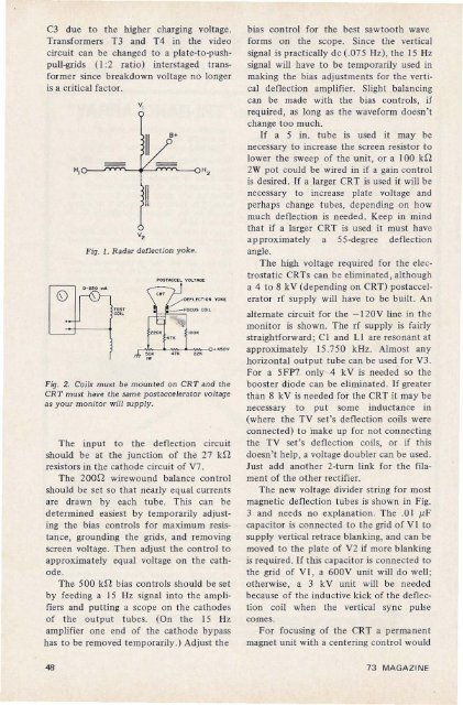
Fig. 1. Radar de flection yo k e.<br />
~<br />
,W<br />
UK 22K<br />
Fig. 2. Coils must be mounted on CR T and the<br />
CR T m ust bave th e same post accelerator voltage<br />
as your monitor will supply .<br />
Th e input to the deflection circuit<br />
should be at the junction of the 27 kn<br />
resistors in the cat hode circuit of V7 .<br />
The 200n wirewound balance control<br />
should be set so that nearl y equal curren ts<br />
are drawn by each tube. This can be<br />
determined easies t by temporarily adjusting<br />
the bias controls for maximum resistan<br />
ce, grou nding th e grid s, and remo ving<br />
screen voltage. Then adjust the contro l to<br />
approximately equa l voltage on the cat h<br />
od e.<br />
Th e 500 kn bias con trols should be set<br />
by feeding a 15 Hz signal into th e amplifiers<br />
and putt ing a scope on the catho des<br />
of t he ou tput tubes. (On the 15 liz<br />
amplifier one end of the catho de by pass<br />
has to be removed temporarily .) Adju st th e<br />
bias co ntrol for the best sawtooth wave<br />
forms on the scope. Since the vertical<br />
signal is practically d c (.07 5 Hz), the 15 Hz<br />
signal will have to be tem porarily used in<br />
making the bias adjustments for the vertical<br />
deflection amp lifier. Slight balancing<br />
can be mad e with the bias controls, if<br />
required , as long as the waveform doesn't<br />
chang e too much.<br />
If a 5 in. tube is used it may be<br />
necessary to increase the scre en resistor to<br />
lower the sweep of the unit, or a 100 kn<br />
2W pot cou ld be wired in if a gain co ntro l<br />
is desired . If a larger CRT is used it will be<br />
necessary to increase plate voltage and<br />
per haps change tub es, dep ending on how<br />
much defl ection is needed . Keep in mind<br />
that if a larger CRT is used it must have<br />
approx ima tely a 55-degree defl ect ion<br />
angle.<br />
The high voltage req uired for the elect<br />
rostatic CRTs can be eliminated , although<br />
a 4 to 8 kV (depending on CRT) po sta ccelera<br />
tor rf supply will have to be built. An<br />
alternate circuit for the - 120V line in th e<br />
monitor is shown. Th e rf supp ly is fairl y<br />
str aightforward ; C I and LI are resonant at<br />
approximately 15.750 kHz. Almost any<br />
horizontal ou tput tube can be used for V3 .<br />
For a 5FP7 only 4 k V is needed so the<br />
booster diode can be eliminated. If greater<br />
than 8 k V is needed for the CRT it may be<br />
necessary to put some inductance in<br />
(where the T V set's deflection coils were<br />
connec te d) to make up for not co nnecting<br />
the TV set's deflection coils, or if this<br />
doesn't help, a voltage doubler can be used .<br />
Ju st add another 2-turn link for th e filament<br />
of the other recti fier.<br />
Th e new volt age divider string for most<br />
magnetic deflection tubes is sho wn in Fig.<br />
3 and needs no explanation. The .01 pF<br />
capacitor is co nnect ed to t he grid of V I to<br />
supply vertical retrace blanking, and can be<br />
mov ed to the plate of V2 if more blanking<br />
is required. If this capacitor is connecte d to<br />
the grid of V I , a 60 0V unit will do well;<br />
otherwise, a 3 k V unit will be need ed<br />
because of the inductive kick of the deflection<br />
coil when the ver tical sync pu lse<br />
comes.<br />
For focusing of the CRT a perman ent<br />
magn et unit with a centering con tro l would<br />
48<br />
73 MA GAZIN E


