Instruction Sheet - Agentur KONSENS
Instruction Sheet - Agentur KONSENS
Instruction Sheet - Agentur KONSENS

Create successful ePaper yourself
Turn your PDF publications into a flip-book with our unique Google optimized e-Paper software.
Information sheet<br />
“Glass and acrylic glass“ (continued)<br />
- The supports used must ensure that glass sheets are not secured<br />
under pressure.<br />
- Taking into account the effects of loads and temperature fluctuations,<br />
contact between glass and other hard materials (e.g. other glass,<br />
metal) may not occur at any time.<br />
- The sections used to support glass sheets must be sufficiently stiff.<br />
Maximum permissible deformation:<br />
Section:<br />
f ≤ lsection/200<br />
f ≤ 15 mm<br />
- <strong>Sheet</strong>:<br />
f ≤ lsheet/100 (l = length of main direction of load)<br />
- Minimum supporting depths of glass sheets on their respective<br />
sections must be adhered to.<br />
- After glazing has been installed it must be possible to identify the<br />
individual type of glass sheet used (e.g. TSG, HSG) at all times. In<br />
the case of LSG glazing, for inspecttion purposes (number of glass<br />
sheets, thickness, interlayer) an area on the edge must be left free<br />
until after construction work has been approved. If required a<br />
manufacturer's certificate should be submitted.<br />
- The edges of glass sheets must be fashioned or protected in such a<br />
way as to exclude any possibility of injuries occurring.<br />
- In the case of TSG, HSG, or LSG glazing manufactured from sheets<br />
of TSG or HSG, subsequent reworking of the finished product such<br />
as cutting out sections or drilling holes is not possible.<br />
- <strong>Sheet</strong>s designed to sustain human loads must safeguard against<br />
persons slipping at all times.<br />
Prior to submission of a standard for glass measurements by the<br />
building inspectorate the stability proofs for unbroken glass should<br />
be carried out according to the following basic rules<br />
- Effects are applied without using partial security co-efficients, proof<br />
of load-bearing capacity takes the form of a proof of the maximum<br />
main ensile stress against the permitted stresses in accordance with<br />
Table 1.<br />
- When considering the stability effect on LSG its compound nature<br />
is ignored. The contribution towards the overall effect made by<br />
each individual sheet of glass is measured.<br />
- In the case of glass which is intended to support human loads the<br />
uppermost layer is regarded as the one subjected to wear and is<br />
not included in the proofs.<br />
- Material tests should be used to substantiate proof concepts for<br />
point-supported glass.<br />
- The notes and references to literature in Appendix E to TRAV<br />
should be taken into consideration (see 9. Literature, [9] [10])<br />
- For examples of proofs see [11]<br />
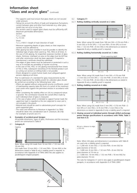
6. Examples of accident-proof designs<br />
All possible dimensions, types of glass, thicknesses and the necessary<br />
proofs are summarised in Table B.<br />
6.1 Category B<br />
Capping<br />
Note: When using LSG made from 10 mm SSG + 1.52 mm PVB<br />
10 mm SSG<br />
LSG made from 10 mm HSG + 1.52 mm PVB + 10 mm HSG in the<br />
dimensions stated in Table B only a stability proof is required. In<br />
accordance with Appendix D of TRAV 2003 this also applies to<br />
parallelogram-shaped parapets:<br />
height<br />
height<br />
railing height must<br />
comply with technical<br />
regulations<br />
6.2 Category C1<br />
6.2.1 Railing cladding vertically secured on 2 sides<br />
Note: When using LSG made from 100 mm SSG + 0.76 mm PVB +<br />
6 mm SSG or 8 mm SPG + 1.52 mm PVB + 8 mm SPG or 8 mm<br />
HSG + 1.52 mm PVB + 8 mm HSG in the dimensions as stated in<br />
Appendix B only a stability proof is required.<br />
6.2.2 Railing cladding horizontally secured on 2 sides<br />
Note: When using LSG made from 5 mm SSG + 0.76 mm PVB<br />
+ 5 mm SSG or 8 mm SPG + 1.52 mm PVB + 8 mm SPG or 8 mm<br />
HSG + 1.52 mm PVB + 8 mm HSG in the dimensions as stated in<br />
Appendix B only a stability proof is required.<br />
6.2.3 Railing cladding secured on 4 sides<br />
35<br />
i4.8<br />
Note: When using LSG made from 5 mm SPG + 0.76 mm PVB + 5<br />
mm SPG or 5 mm HSG + 0.76 mm PVB + 5 mm HSG in the<br />
dimensions as stated in Appendix B only a stability proof is required.<br />
6.2.4 Glazing secured at individual points through drilled anchorage<br />
points (design specifications in accordance with TRAV, Table 3<br />
and Item 6.3)<br />
80 mm ≤ distance to edge<br />
≤ 250 mm<br />
18 mm supporting depth<br />
railing height must<br />
comply with technical<br />
regulations<br />
railing height must<br />
comply with technical<br />
regulations<br />
railing height must<br />
comply with technical<br />
regulations<br />
railing height must<br />
comply with technical<br />
regulations<br />
Note: When LSG glass and dimensions in accordance with Table B<br />
are used only a stability proof is required:<br />
L < 1,200 mm: 6 mm SSG + 1.52 mm PVB + 6 mm SSG for<br />
plate diameter of 50 mm<br />
L < 1,600 mm: 8 mm SSG + 1.52 mm PVB + 8 mm SSG for<br />
plate diameter of 70 mm or<br />
L < 1,600 mm: 10 mm HSG + 1.52 mm PVB + 10 mm HSG for<br />
plate diameter 70 mm<br />
The rules for Categories C1 and C2 also apply to parallelogram-shaped<br />
parapets, in accordance with Appendix D of TRAV 2003:<br />
Please turn over!<br />
35