Operating Manual LUXOR S 400
Operating Manual LUXOR S 400
Operating Manual LUXOR S 400

Create successful ePaper yourself
Turn your PDF publications into a flip-book with our unique Google optimized e-Paper software.
<strong>LUXOR</strong> S <strong>400</strong><br />
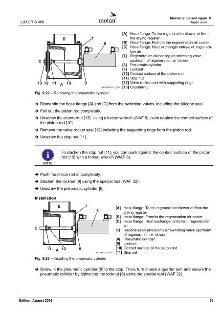
Fig. 9.22 – Removing the pneumatic cylinder<br />
Maintenance and repair 9<br />
Repair work<br />
� Dismantle the hose flange [A] and [C] from the switching valves, including the silicone seal.<br />
� Pull out the piston rod completely.<br />
� Unscrew the counternut [13]. Using a forked wrench (WAF 8), push against the contact surface of<br />
the piston rod [10].<br />
� Remove the valve rocker seal [12] including the supporting rings from the piston rod.<br />
� Unscrew the stop nut [11].<br />
NOTE<br />
� Push the piston rod in completely.<br />
� Slacken the locknut [9] using the special tool (WAF 32).<br />
� Unscrew the pneumatic cylinder [8].<br />
Installation<br />
[A] Hose flange: To the regeneration blower or from<br />
the drying register<br />
[B] Hose flange: From/to the regeneration air cooler<br />
[C] Hose flange: Heat exchanger entry/exit, regeneration<br />
air<br />
[7] Regeneration air/cooling air switching valve<br />
upstream of regeneration air blower<br />
[8] Pneumatic cylinder<br />
[9] Locknut<br />
[10] Contact surface of the piston rod<br />
[11] Stop nut<br />
[12] Valve rocker seal with supporting rings<br />
[13] Counternut<br />
To slacken the stop nut [11], you can push against the contact surface of the piston<br />
rod [10] with a forked wrench (WAF 8).<br />
Fig. 9.23 – Installing the pneumatic cylinder<br />
[A] Hose flange: To the regeneration blower or from the<br />
drying register<br />
[B] Hose flange: From/to the regeneration air cooler<br />
[C] Hose flange: Heat exchanger entry/exit, regeneration<br />
air<br />
[7] Regeneration air/cooling air switching valve upstream<br />
of regeneration air blower<br />
[8] Pneumatic cylinder<br />
[9] Locknut<br />
[10] Contact surface of the piston rod<br />
[11] Stop nut<br />
� Screw in the pneumatic cylinder [8] to the stop. Then, turn it back a quarter turn and secure the<br />
pneumatic cylinder by tightening the locknut [9] using the special tool (WAF 32).<br />
Edition: August 2005 63