Remaining Life of a Pipeline

You also want an ePaper? Increase the reach of your titles
YUMPU automatically turns print PDFs into web optimized ePapers that Google loves.
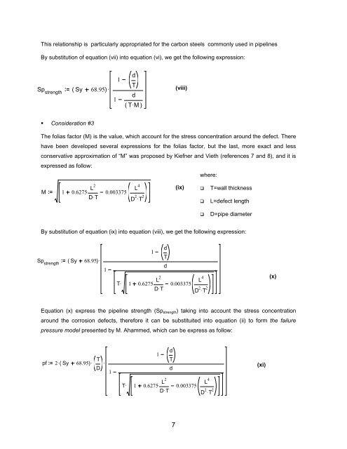
This relationship is particularly appropriated for the carbon steels commonly used in pipelines<br />
By substitution <strong>of</strong> equation (vii) into equation (vi), we get the following expression:<br />
d<br />
1<br />
T<br />
Sp strength<br />
( Sy 68.95)<br />
. (viii)<br />
d<br />
1<br />
( TM . )<br />
• Consideration #3<br />
The folias factor (M) is the value, which account for the stress concentration around the defect. There<br />
have been developed several expressions for the folias factor, but the last, more exact and less<br />
conservative approximation <strong>of</strong> “M” was proposed by Kiefner and Vieth (references 7 and 8), and it is<br />
expressed as follow:<br />
where:<br />
M 1 0.6275. L2<br />
DT . 0.003375.<br />
L 4<br />
D 2 . T 2<br />
(ix)<br />
<br />
<br />
T=wall thickness<br />
L=defect length<br />
<br />
D=pipe diameter<br />
By substitution <strong>of</strong> equation (ix) into equation (viii), we get the following expression:<br />
Sp strength<br />
( Sy 68.95)<br />
.<br />
1<br />
d<br />
1<br />
T<br />
d<br />
T.<br />
1 0.6275. L2<br />
DT . 0.003375.<br />
L 4<br />
D 2 . T 2<br />
(x)<br />
Equation (x) express the pipeline strength (Sp strength ) taking into account the stress concentration<br />
around the corrosion defects, therefore it can be substituited into equation (ii) to form the failure<br />
pressure model presented by M. Ahammed, which can be express as follow:<br />
pf 2. T<br />
( Sy 68.95)<br />
.<br />
D<br />
.<br />
1<br />
d<br />
1<br />
T<br />
d<br />
T.<br />
1 0.6275. L2<br />
DT . 0.003375.<br />
L 4<br />
D 2 . T 2<br />
(xi)<br />
7