

ALUMINUM ELECTROLYTIC CAPACITORS
ALUMINUM ELECTROLYTIC CAPACITORS
ALUMINUM ELECTROLYTIC CAPACITORS

You also want an ePaper? Increase the reach of your titles
YUMPU automatically turns print PDFs into web optimized ePapers that Google loves.
a<br />
CONDUCTIVE POLYMER <strong>ALUMINUM</strong> SOLID <strong>CAPACITORS</strong> Surface Mount<br />
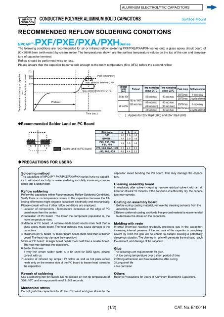
RECOMMENDED REFLOW SOLDERING CONDITIONS<br />
The following conditions are recommended for air or infrared refl ow soldering PXF/PXE/PXA/PXH series onto a glass epoxy circuit board of<br />
90B50B0.8mm (with resist) by cream solder. The temperatures shown are the surface temperature values on the top of the can and tem per ature<br />
of capacitor terminal.<br />
Refl ow should be performed twice or less.<br />
Please ensure that the capacitor became cold enough to the room temperature (5 to 35C) before the second refl ow.<br />
Temperature on the top of capacitor<br />
and<br />
Temperature of capacitor terminal<br />
(C)<br />
Peak<br />
230<br />
217<br />
@Recommended Solder Land on PC Board<br />
b<br />
c<br />
Preheat<br />
?PRECAUTIONS FOR USERS<br />
Solder land on PC board<br />
Time (sec.)<br />
Peak temperature<br />
Max. period of time over 230C<br />
Max. period of time over 217C<br />
Size code<br />
D55<br />
E60,E61<br />
F45, F55, F60<br />
F61, F80<br />
H70, H80, HA0, HC0<br />
J80, JA0, JC0<br />
Soldering method<br />
The capacitors of NPCAP TM -PXF/PXE/PXA/PXH series have no capability<br />
to with stand such dip or wave soldering as totally immersing components<br />
into a sol der bath.<br />
Refl ow soldering<br />
Refl ow the capacitors within Recommended Refl ow Soldering Con di tions.<br />
Verify there is no temperature stress to the capacitors because the follow<br />
ing dif fer enc es might degrade capacitors electrically and mechanically.<br />
Please con sult with us if other refl ow conditions are employed.<br />
1.Location of components : Temperature increases at the edge of PC<br />
board more than the center.<br />
2.Population of PC board : The lower the component population is, the<br />
more temperature rises.<br />
3.Material of PC board : A ceramic-made board needs more heat than a<br />
glass epoxy-made board. The heat increase may cause damage to the<br />
capacitors.<br />
4.Thickness of PC board : A thicker board needs more heat than a thinner<br />
board. The heat may damage the capacitors.<br />
5.Size of PC board : A larger board needs more heat than a smaller board.<br />
The heat may damage the capacitors.<br />
6.Solder thickness<br />
If very thin cream solder paste is to be used for SMD types, please<br />
consult with us.<br />
7.Location of infrared ray lamps : IR refl ow as well as hot plate refl ow<br />
heats only on the reverse side of the PC board to lessen heat stress to<br />
the capacitors.<br />
Rework of soldering<br />
Use a soldering iron for rework. Do not exceed an iron tip temperature of<br />
380P10C and an exposure time of 3P0.5 sec onds.<br />
Mechanical stress<br />
Do not grab the capacitors to lift the PC board and give stress to the<br />
(1/2)<br />
Voltage<br />
range<br />
(Vdc)<br />
2.5 to 16V<br />
20 to 25V<br />
a<br />
1.0<br />
1.4<br />
1.9<br />
3.1<br />
4.5<br />
150 to 180C<br />
120 sec.max.<br />
b<br />
2.6<br />
3.0<br />
3.5<br />
4.2<br />
4.4<br />
Time maintained Time maintained<br />
Preheat Peak temp. Reflow number<br />
above 217c above 230c<br />
c<br />
1.6<br />
1.6<br />
1.6<br />
2.2<br />
2.2<br />
50 sec.max.<br />
50 sec.max.<br />
(40 sec.max.)<br />
40 sec.max.<br />
40 sec.max.<br />
40 sec.max.<br />
(30 sec.max.)<br />
30 sec.max.<br />
ca pac i tor. Avoid bending the PC board. This may damage the ca pac itors.<br />
Cleaning assembly board<br />
Immediately after solvent cleaning, remove residual solvent with an air<br />
knife for at least 10 minutes. If the solvent is insuffi ciently dry, the capacitors<br />
may corrode.<br />
Coating on assembly board<br />
1.Before curing coating material, remove the cleaning solvents from the<br />
assembly board.<br />
2.Before conformal coating, a chloride free pre-coat material is rec om mend ed<br />
to decrease the stress on the capacitors.<br />
Molding with resin<br />
Internal chemical reaction gradually produces gas in the capacitor;<br />
increasing internal pressure. If the end seal of the capacitor is com plete ly<br />
coverd by resin the gas will be unable to escape causing a potentially<br />
dangerous situation. The chlorine in resin will penetrate the end seal, reach<br />
the element, and damage of the capacitor.<br />
Glue<br />
The followings are requirements for glue.<br />
1.A low curing temperature over a short period of time<br />
2.Strong adhension and heat resistance after curing<br />
3.Long shelf life<br />
4.No corrosion<br />
260Cmax.<br />
250Cmax.<br />
250Cmax.<br />
(240Cmax.)<br />
( ) : Applies for 20V 82MF(J80) and 25V 39MF(J80)<br />
Others<br />
Refer to Precautions for Users of Aluminum Electrolytic Capacitors.<br />
1-cycle only<br />
2-cycle allowed<br />
1-cycle only<br />
2-cycle allowed<br />
CAT. No. E1001H


