

ALUMINUM ELECTROLYTIC CAPACITORS
ALUMINUM ELECTROLYTIC CAPACITORS
ALUMINUM ELECTROLYTIC CAPACITORS

You also want an ePaper? Increase the reach of your titles
YUMPU automatically turns print PDFs into web optimized ePapers that Google loves.
PRECAUTIONS AND GUIDELINES<br />
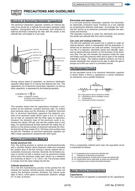
Structure of Aluminum Electrolytic Capacitors<br />
The aluminum electrolytic capacitor contains an internal el e -<br />
ment of an anode foil, a cathode foil and paper separator rolled<br />
to geth er, impregnated with an elec tro lyte, then attached to<br />
ex ter nal ter mi nals con nect ing the tabs with the anode or the<br />
cath ode foils, and sealed in a can case.<br />
Lead Wire<br />
Aluminum Tab<br />
Separator Paper<br />
Cathode Foil<br />
Anode Foil<br />
Among various types of capacitors, an aluminum elec tro lyt ic<br />
ca pac i tor offers large CV to volume and features low cost. The<br />
ca pac i tance (C) of alu mi num electrolytic capacitors, as well as<br />
oth er capacitors, is ex pressed by the following equa tion:<br />
C=8.854B10 -12 B (F)<br />
Where : ε=Dielectric constant<br />
S=Surface area of dielectric (m2) εS<br />
d<br />
d=Thickness of dielectric (m)<br />
This equation shows that the capacitance in creas es in propor<br />
tion as the dielectric constant becomes high, its surface<br />
area becomes large and the thick ness of dielectric becomes<br />
thin. In aluminum elec tro lyt ic ca pac i tors the dielectric constant<br />
of an alu mi num oxide (Al2O3) layer is 8 to 10, which is<br />
not as high as compared with the other types of ca pac i tors.<br />
However, the di elec tric layer of the aluminum oxide is extreme<br />
ly thin (about 15Å per volt) and the surface area is very<br />
large. An electrochemical formed electrode foil makes the dielec<br />
tric on the etched surface of aluminum electrode foil. Electro<br />
chem i cal etching cre ates 20 to 100 times more surface area<br />
as plain foil. There fore, an alu mi num elec tro lyt ic capacitor can<br />
offer a large capacitance compared with other types.<br />
Primary of Composition Material<br />
Lead Wire<br />
Aluminum Tab<br />
Rubber Seal<br />
Sleeve<br />
Can<br />
Element<br />
Anode aluminum foil:<br />
First, the etching process is carried out electromechanically<br />
with a chlo ride solution which dissolves metal and increases<br />
the sur face area of the foil; forming a dense net work like innu<br />
mer a ble mi cro scop ic chan nels. Secondly, the for ma tion process<br />
is carried out with a solution such as ammonium bo rate<br />
which forms the alu mi num ox ide layer (Al2O3) as a di elec tric<br />
at a thick ness of about 1.1 to 1.5nm / volt. The pro cess needs<br />
to charge more the rated volt age into the foil.<br />
Cathode aluminum foil:<br />
As in the fi rst manufacturing process of the pos i tive foil, the<br />
cath ode foil requires etching process. Generally, it does not<br />
re quire the for ma tion process; therefore, the natural ox ide<br />
lay er of Al2O3, which gives a characteristic dielectric voltage<br />
of 1.0 volts, is formed.<br />
(4/10)<br />
Electrolyte and separator:<br />
In a non-solid aluminum electrolytic capacitor, the elec tro lyte,<br />
an electrically conductive liquid, func tions as a true cathode<br />
by con tact ing the dielectric oxide layer. Accordingly, the “cathode<br />
foil” serves as an electrical connection between the electro<br />
lyte and ter mi nal.<br />
The separator functions to retain the electrolyte and prevent<br />
the anode and cathode foils from short-cir cuit ing.<br />
Can case and sealing materials:<br />
The foils and separator are wound into a cylinder to make an<br />
internal element, which is impregnated with the electrolyte, insert<br />
ed into an aluminum can case and sealed. During the service<br />
life of a ca pac i tor, electrolyte slowly and naturally va por -<br />
iz es by elec tro chem i cal reaction on the boundary of the alu mi -<br />
num foils. The gas will increase the pressure inside the case<br />
and fi nally cause the pressure relief vent to open or the seal ing<br />
materials to bulge. The sealing material func tions not only to<br />
prevent elec tro lyte from drying out but also to al low the gas to<br />
escape out of the can case in a controlled manner.<br />
The Equivalent Circuit<br />
As the equivalent circuit of an aluminum electrolytic capacitor<br />
is shown below, it forms a capacitance, a series resistance,<br />
an in duc tance, and a parallel resistance.<br />
Lan<br />
Anode foil<br />
Dan<br />
Can<br />
Ran<br />
Dielectric (Al2O3)<br />
Separator<br />
From a composition material point wise, the equivalent cir cuit<br />
is sub di vid ed as follows.<br />
Basic Electrical Characteristics<br />
R<br />
RLC<br />
RESR C LESL<br />
RESR=Equivalent series resistance (ESR)<br />
RLC =Resistance due to leakage current<br />
C =Capacitance<br />
LESL =Equivalent series inductance<br />
Electrolyte<br />
Can, CCa=Capacitance due to anode and cathodes foils<br />
R =Resistance of electrolyte and separator<br />
Ran, RCa=Internal resistance of oxide layer on anode and cathode foils<br />
Dan, DCa=Diode effects due to oxide layer on anode and cathode foils<br />
Lan, LCa =Inductance due to anode and cathode terminals<br />
Capacitance:<br />
The capacitance of capacitor is expressed as AC ca pac i tance<br />
Dca<br />
Cca<br />
Rca<br />
Cathode foil<br />
Lca<br />
CAT. No. E1001H


