

ALUMINUM ELECTROLYTIC CAPACITORS
ALUMINUM ELECTROLYTIC CAPACITORS
ALUMINUM ELECTROLYTIC CAPACITORS

Create successful ePaper yourself
Turn your PDF publications into a flip-book with our unique Google optimized e-Paper software.
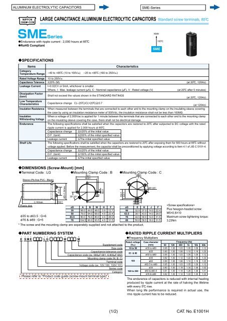
LARGE CAPACITANCE <strong>ALUMINUM</strong> <strong>ELECTROLYTIC</strong> <strong>CAPACITORS</strong> Standard screw terminals, 85C<br />
@Endurance with ripple current : 2,000 hours at 85C<br />
@RoHS Compliant<br />
?SPECIFICATIONS<br />
Items<br />
Category<br />
Temperature Range<br />
Rated Voltage Range<br />
Capacitance Tolerance<br />
Leakage Current<br />
Dissipation Factor<br />
(tane)<br />
Low Temperature<br />
Characteristics<br />
Insulation Resistance<br />
Insulation<br />
Withstanding Voltage<br />
Endurance<br />
Shelf Life<br />
Characteristics<br />
-40 to +85C (10 to 100Vdc) -25 to +85C (160 to 250Vdc)<br />
10 to 250Vdc<br />
P20% (M)<br />
(at 20C, 120Hz)<br />
I=0.02CV or 5mA, whichever is smaller.<br />
Where, I : Max. leakage current (MA), C : Nominal capacitance (MF), V : Rated voltage (V)<br />
(at 20C after 5 minutes)<br />
Shall not exceed the values shown in the STANDARD RATINGS<br />
(at 20C, 120Hz)<br />
Capacitance change C(-25C)/C(+20C)]0.7<br />
(at 120Hz)<br />
When measured between the terminals that are connected to each other and to the mounting clamp on the insulating sleeve covering<br />
the case by using an insulation resistance meter of 500Vdc, the insulation resistance shall not be less than 100MO.<br />
When a voltage of 2,000Vac is applied for 1 minute between the terminals that are connected to each other and to the mounting clamp<br />
on the insulating sleeve covering the case, there shall not be electrical damage.<br />
The following specifications shall be satisfied when the capacitors are restored to 20C after subjected to DC voltage with the rated<br />
ripple current is applied for 2,000 hours at 85C.<br />
Capacitance change [P20% of the initial value<br />
D.F. (tanE) [200% of the initial specified value<br />
Leakage current [The initial specified value<br />
The following specifications shall be satisfied when the capacitors are restored to 20C after exposing them for 500 hours at 85C without<br />
voltage applied. Before the measurement, the capacitor shall be preconditioned by applying voltage according to Item 4.1 of JIS C 5101-4.<br />
Capacitance change [P20% of the initial value<br />
D.F. (tanE) [150% of the initial specified value<br />
Leakage current [The initial specified value<br />
?DIMENSIONS (Screw-Mount) [mm]<br />
@Terminal Code : LG<br />
@Mounting Clamp Code : B<br />
Sleeve (Pb-free PVC : Black)<br />
Plastic disk<br />
F35 to F63.5 : G=6<br />
F76 & F89 : G=5<br />
FP1<br />
L+4max. GP1<br />
FD+1.8max.<br />
30°P5°<br />
fD<br />
35<br />
50<br />
63.5<br />
76<br />
* The screw and the mounting clamp are separately supplied and not attached to the product.<br />
?PART NUMBERING SYSTEM<br />
1 2 3 4 5 6 7 8 9 10 11 12 13<br />
E S M E A A A L G N A A A<br />
14<br />
M<br />
15 16 17 18<br />
A A A M<br />
A<br />
58.0<br />
78.0<br />
90.0<br />
104.5<br />
AP1<br />
WP1<br />
B<br />
44.0<br />
64.0<br />
76.0<br />
90.0<br />
6<br />
W<br />
48.0<br />
68.0<br />
80.0<br />
93.5<br />
H<br />
BP1<br />
H<br />
3.5<br />
4.5<br />
4.5<br />
4.5<br />
F<br />
12.7<br />
22.4<br />
28.0<br />
31.5<br />
Supplement code<br />
Size code<br />
Capacitance tolerance code<br />
Capacitance code (ex. 680MF:681, 6,800MF:682)<br />
Mounting clamp code (N, B, C)<br />
Terminal code<br />
Voltage code (ex. 10V:100, 100V:101)<br />
Series code<br />
Category<br />
Please refer to "Product code guide (screw-mount terminal type)"<br />
(1/2)<br />
@Mounting Clamp Code : C<br />
KP1<br />
EP1<br />
fD<br />
50<br />
63.5<br />
76<br />
89<br />
8<br />
J<br />
?RATED RIPPLE CURRENT MULTIPLIERS<br />
@Frequency Multipliers<br />
Rated voltage<br />
(Vdc)<br />
10 to 50<br />
63 & 80<br />
100<br />
E<br />
32.5<br />
38.1<br />
44.5<br />
50.8<br />
160 to 250<br />
360°<br />
3<br />
4.5<br />
K<br />
37.0<br />
43.5<br />
50.0<br />
56.5<br />
45°P5°<br />
J<br />
14.0<br />
14.0<br />
14.0<br />
16.0<br />
KMH<br />
SME<br />
Case diameter<br />
(mm)<br />
F35 to F89<br />
F35<br />
F50 to F89<br />
F35<br />
F50<br />
F63.5 to F89<br />
F35<br />
F50 & F63.5<br />
F76 & F89<br />
105C<br />
F<br />
22.4<br />
28.0<br />
31.5<br />
31.5<br />
Frequency (Hz)<br />
50 120 300 1k 10k 50k<br />
0.95<br />
0.90<br />
0.95<br />
0.82<br />
0.90<br />
0.95<br />
0.80<br />
0.81<br />
0.82<br />
<br />
Plus hexagon-headed screw:<br />
M5B0.8B10<br />
Maximum screw tight en ing torque:<br />
3.23Nm<br />
1.00<br />
1.00<br />
1.00<br />
1.00<br />
1.00<br />
1.00<br />
1.00<br />
1.00<br />
1.00<br />
1.03<br />
1.06<br />
1.03<br />
1.12<br />
1.06<br />
1.03<br />
1.19<br />
1.14<br />
1.12<br />
1.05<br />
1.10<br />
1.05<br />
1.22<br />
1.10<br />
1.05<br />
1.34<br />
1.26<br />
1.22<br />
1.09<br />
1.18<br />
1.09<br />
1.30<br />
1.18<br />
1.09<br />
1.46<br />
1.36<br />
1.30<br />
1.12<br />
1.22<br />
1.12<br />
1.33<br />
1.22<br />
1.12<br />
1.52<br />
1.41<br />
1.33<br />
The endurance of capacitors is reduced with internal heating<br />
produced by ripple current at the rate of halving the lifetime<br />
with every 5C rise.<br />
When long life performance is required in actual use, the<br />
rms ripple current has to be reduced.<br />
CAT. No. E1001H


