

ALUMINUM ELECTROLYTIC CAPACITORS
ALUMINUM ELECTROLYTIC CAPACITORS
ALUMINUM ELECTROLYTIC CAPACITORS

Create successful ePaper yourself
Turn your PDF publications into a flip-book with our unique Google optimized e-Paper software.
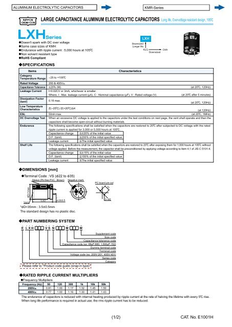
LARGE CAPACITANCE <strong>ALUMINUM</strong> <strong>ELECTROLYTIC</strong> <strong>CAPACITORS</strong> Long life, Overvoltage resistant design, 105C<br />
@Doesn't spark with DC over voltage<br />
@Same case sizes of KMH<br />
@Endurance with ripple current : 5,000 hours at 105C<br />
@Non solvent resistant type<br />
@RoHS Compliant<br />
?SPECIFICATIONS<br />
Category<br />
Temperature Range<br />
Rated Voltage<br />
Capacitance Tolerance<br />
Leakage Current<br />
Dissipation Factor<br />
(tane)<br />
Low Temperature<br />
Characteristics<br />
ESL<br />
DC Overvoltage Test<br />
Endurance<br />
Shelf Life<br />
Items<br />
?DIMENSIONS [mm]<br />
@Terminal Code : VS (F22 to F35)<br />
FD+1max.<br />
Vent<br />
?PART NUMBERING SYSTEM<br />
Characteristics<br />
-25 to +105C<br />
200 & 400Vdc<br />
P20% (M)<br />
(at 20C, 120Hz)<br />
I=0.02CV or 3mA, whichever is smaller.<br />
Where, I : Max. leakage current (MA), C : Nominal capacitance (MF), V : Rated voltage (V)<br />
(at 20C after 5 minutes)<br />
0.15 max.<br />
(at 20C, 120Hz)<br />
Z(-25C) /Z(+20C)[4<br />
(at 120Hz)<br />
50nH max.<br />
(at 20C, 1MHz)<br />
When an excessive DC voltage is applied to the capacitors under the test conditions on next page, the vent shall operate and then the<br />
capacitors shall become open-circuit without burning materials.<br />
The following specifications shall be satisfied when the capacitors are restored to 20C after subjected to DC voltage with the rated<br />
ripple current is applied for 3,000 or 5,000 hours at 105C.<br />
Capacitance change [P20% of the initial value<br />
D.F. (tanE) [200% of the initial specified value<br />
Leakage current [The initial specified value<br />
The following specifications shall be satisfied when the capacitors are restored to 20C after exposing them for 1,000 hours at 105C without<br />
voltage applied. Before the measurement, the capacitor shall be preconditioned by applying voltage according to Item 4.1 of JIS C 5101-4.<br />
Capacitance change [P15% of the initial value<br />
D.F. (tanE) [150% of the initial specified value<br />
Leakage current [The initial specified value<br />
Sleeve (Pb-free PVC : Brown)<br />
?RATED RIPPLE CURRENT MULTIPLIERS<br />
@Frequency Mul ti pli ers<br />
Frequency (Hz)<br />
200Vdc<br />
400Vdc<br />
LP2<br />
50<br />
0.81<br />
0.77<br />
*<br />
4.0P0.5<br />
120<br />
1.00<br />
1.00<br />
Negative mark<br />
*FD=35mm : 3.5P0.5mm<br />
The standard design has no plastic disc.<br />
1 2 3 4 5 6 7 8 9 10 11 12 13 14 15 16 17 18<br />
E L X H A A A V S N A A A M A A A M<br />
300<br />
1.17<br />
1.16<br />
1k<br />
1.32<br />
1.30<br />
10k<br />
1.45<br />
1.41<br />
PC board pin-out<br />
50k<br />
1.50<br />
1.43<br />
10<br />
2-F2<br />
Supplement code<br />
Size code<br />
Capacitance tolerance code<br />
Capacitance code (ex. 68MF:680, 1,500MF:152)<br />
Dummy terminal code<br />
Terminal code<br />
Voltage code (ex. 200V:201, 400V:401)<br />
Series code<br />
Category<br />
Please refer to "Product code guide (snap-in type)"<br />
LXH<br />
Downsized<br />
Longer life<br />
KLG CHA<br />
Downsized<br />
The endurance of capacitors is reduced with internal heating produced by ripple current at the rate of halving the lifetime with every 5C rise.<br />
When long life performance is required in actual use, the rms ripple current has to be reduced.<br />
(1/2)<br />
CAT. No. E1001H


