

ALUMINUM ELECTROLYTIC CAPACITORS
ALUMINUM ELECTROLYTIC CAPACITORS
ALUMINUM ELECTROLYTIC CAPACITORS

Create successful ePaper yourself
Turn your PDF publications into a flip-book with our unique Google optimized e-Paper software.
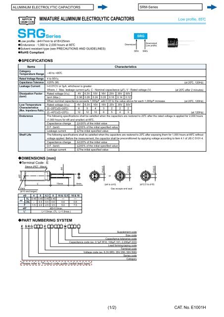
MINIATURE <strong>ALUMINUM</strong> <strong>ELECTROLYTIC</strong> <strong>CAPACITORS</strong> Low profi le, 85C<br />
@Low profi le : F4B7mm to F18B25mm<br />
@Endurance : 1,000 to 2,000 hours at 85C<br />
@Solvent resistant type (see PRECAUTIONS AND GUIDELINES)<br />
@RoHS Compliant<br />
?SPECIFICATIONS<br />
Category<br />
Temperature Range<br />
Rated Voltage Range<br />
Capacitance Tolerance<br />
Leakage Current<br />
Dissipation Factor<br />
(tane)<br />
Low Temperature<br />
Characteristics<br />
(Max. Impedance Ratio)<br />
Endurance<br />
Shelf Life<br />
Items<br />
-40 to +85C<br />
?DIMENSIONS [mm]<br />
@Terminal Code : E<br />
FD'<br />
Sleeve (PET : Black)<br />
4 to 50Vdc<br />
P20% (M)<br />
I=0.01CV or 3MA, whichever is greater.<br />
Where, I : Max. leakage current (MA), C : Nominal capacitance (MF), V : Rated voltage (V)<br />
Rated voltage (Vdc)<br />
tanE (Max.)<br />
?PART NUMBERING SYSTEM<br />
4V<br />
0.38<br />
6.3V<br />
0.28<br />
10V<br />
0.24<br />
16V<br />
0.20<br />
25V<br />
0.16<br />
Characteristics<br />
35V<br />
0.14<br />
Downsized<br />
50V<br />
0.12<br />
Downsized<br />
Low profile<br />
(at 20C, 120Hz)<br />
(at 20C after 2 minutes)<br />
When nominal capacitance exceeds 1,000MF, add 0.03 to the value above for each 1,000MF increase.<br />
(at 20C, 120Hz)<br />
Rated voltage (Vdc) 4V 6.3V 10V 16V 25V 35V 50V<br />
Z(-25C)/Z(+20C) 6 5 4 3 2 2 2<br />
Z(-40C)/Z(+20C) 12 12 10 8 5 4 3<br />
(at 120Hz)<br />
The following specifications shall be satisfied when the capacitors are restored to 20C after the rated voltage is applied for 2,000 hours<br />
(1,000 hours for F8 and smaller) at 85C.<br />
Capacitance change [P20% of the initial value<br />
D.F. (tanE) [200% of the initial specified value<br />
Leakage current [The initial specified value<br />
The following specifications shall be satisfied when the capacitors are restored to 20C after exposing them for 1,000 hours at 85C without<br />
voltage applied. Before the measurement, the capacitor shall be preconditioned by applying voltage according to Item 4.1 of JIS C 5101-4.<br />
Capacitance change [P20% of the initial value<br />
D.F. (tanE) [200% of the initial specified value<br />
Leakage current [The initial specified value<br />
L' 15min. 4min.<br />
Vent<br />
(F10 and larger)<br />
fD 4 5 6.3 8 10 & 12.5 16 & 18<br />
fd<br />
7L<br />
]9L<br />
0.45 0.45<br />
- 0.5<br />
0.45<br />
0.5<br />
0.45<br />
0.6<br />
-<br />
0.6<br />
-<br />
0.8<br />
F 1.5 2.0 2.5 3.5 5.0 7.5<br />
fD'<br />
FD+0.5max.<br />
L'<br />
L+1.5max. (7L : L+1.0max.)<br />
Fd<br />
1 2 3 4 5 6 7 8 9 10 11 12 13 14 15 16 17 18<br />
E S R G A A A E A A A A A M A A A D<br />
Please refer to "Product code guide (radial lead type)"<br />
FP0.5<br />
or<br />
(F4 to F10)<br />
FP0.5<br />
Gas escape end seal<br />
Supplement code<br />
Size code<br />
Capacitance tolerance code<br />
Capacitance code (ex. 0.1MF:R10, 100MF:101, 2,200MF:222)<br />
Lead forming·taping code<br />
Terminal code<br />
Voltage code (ex. 6.3V:6R3, 35V:350, 50V:500)<br />
Series code<br />
Category<br />
(1/2)<br />
SRA<br />
SRG<br />
SMG<br />
FP0.5<br />
(F12.5 to F18)<br />
CAT. No. E1001H


