

Alexander (Sandy) Marquardt, Vaughn Betz, and Jonathan Rose
Alexander (Sandy) Marquardt, Vaughn Betz, and Jonathan Rose
Alexander (Sandy) Marquardt, Vaughn Betz, and Jonathan Rose

You also want an ePaper? Increase the reach of your titles
YUMPU automatically turns print PDFs into web optimized ePapers that Google loves.
Routing Segment<br />
A B C<br />
....<br />
Fc<br />
{<br />
Input<br />
Connection<br />
Buffers<br />
& Muxes<br />
{ ....<br />
....<br />
minimum spacing to another transistor above it <strong>and</strong> to its right [8].<br />
By counting the number of minimum-width transistor areas<br />
required to implement an FPGA, rather than the number of square<br />
microns which these transistors would occupy, we obtain a process-independent<br />
estimate of the FPGA area. The area model that<br />
we use is described in detail in [8][9].<br />
We use a program called TransCount [9], to determine the area of a<br />
cluster-based logic block (including the local cluster routing) with<br />
any values of N, I, K, <strong>and</strong> M clk . This program models such effects<br />
as buffer resizing as a function of the fanout of the connections<br />
within a logic block, <strong>and</strong> builds multi-stage buffers when high<br />
drive strengths are required. Since the area of an FPGA includes<br />
both logic block area <strong>and</strong> routing area, we use VPR to determine<br />
the transistor-count of the area taken by the routing for each FPGA<br />
of interest, <strong>and</strong> by adding this area to the logic block area we obtain<br />
the total FPGA area.<br />
4.2 DELAY MODEL<br />
Local<br />
Buffers<br />
Local<br />
Routing<br />
Muxes<br />
{<br />
4<br />
LUT<br />
....<br />
Logic Cluster<br />
BLE<br />
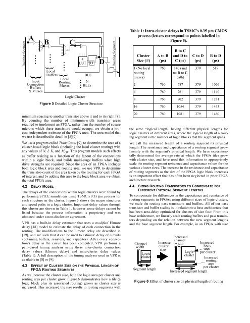
The delays of the connections within logic clusters were found by<br />
performing SPICE simulations using TSMC’s 0.35 μm process for<br />
each structure in the cluster. Figure 5 shows the major structures<br />
<strong>and</strong> speed paths in a logic cluster. Important delay values through<br />
this cluster are shown in Table 1, however some delays cannot be<br />
listed because the process information is proprietary <strong>and</strong> was<br />
obtained under a non-disclosure agreement.<br />
VPR has a built-in delay estimator that uses a modified Elmore<br />
delay [18] model to estimate the delay of each connection in the<br />
routing. The modifications to the Elmore delay are described in<br />
[19], <strong>and</strong> are such that it can be used to estimate delay of circuits<br />
containing buffers, resistors, <strong>and</strong> capacitors. After every connection’s<br />
delay in the circuit has been computed, VPR performs a<br />
path-based timing analysis using these inter-cluster connection<br />
delay values (Elmore delay) <strong>and</strong> intra-cluster delay values<br />
(Table 1). A full description of the timing analyzer used in VPR is<br />
available in [8] or [9].<br />
4.3 EFFECT OF CLUSTER SIZE ON THE PHYSICAL LENGTH OF<br />
FPGA ROUTING SEGMENTS<br />
As we increase the cluster size, both the logic area per cluster <strong>and</strong><br />
routing area per cluster grow. Figure 6 demonstrates how a tile (a<br />
logic block plus its associated routing) grows as cluster size is<br />
increased. This increased tile size results in routing segments with<br />
FF<br />
N<br />
BLEs<br />
D<br />
Figure 5 Detailed Logic Cluster Structure<br />
Routing Segment<br />
Table 1: Intra-cluster delays in TSMC’s 0.35 μm CMOS<br />
process (letters correspond to points labelled in<br />
Figure 5).<br />
Cluster<br />
Size (N)<br />
1 (No local<br />
routing<br />
muxes)<br />
A to B<br />
(ps)<br />
B to C<br />
<strong>and</strong> D to<br />
C (ps)<br />
760 140 (<strong>and</strong><br />
no D to C<br />
path)<br />
C to D<br />
(ps)<br />
B to D<br />
(ps)<br />
379 519<br />
2 760 687 379 1066<br />
4 760 761 379 1140<br />
8 760 902 379 1281<br />
16 760 1054 379 1433<br />
20 760 1081 379 1460<br />
the same “logical length” having different physical lengths for<br />
logic clusters of different sizes, where the logical length of a routing<br />
segment is the number of logic blocks that the segment spans.<br />
We call the measured length of a routing segment its physical<br />
length. The resistance <strong>and</strong> capacitance of a routing segment grow<br />
linearly with the segment’s physical length. We have experimentally<br />
determined the average rate at which the FPGA tiles grow<br />
with cluster size, <strong>and</strong> have used this information to appropriately<br />
scale the routing segment resistance <strong>and</strong> capacitance values for the<br />
various cluster sizes. The increase in the resistance <strong>and</strong> capacitance<br />
of routing segments as the size of the FPGA logic block increases<br />
is an important effect that has often been neglected in prior FPGA<br />
architecture research.<br />
4.4 SIZING ROUTING TRANSISTORS TO COMPENSATE FOR<br />
DIFFERENT PHYSICAL SEGMENT LENGTHS<br />
To compensate for differences in the capacitance <strong>and</strong> resistance of<br />
routing segments in FPGAs using different sizes of logic clusters,<br />
we scale the routing pass transistors <strong>and</strong> buffers. All of our pass<br />
transistor <strong>and</strong> buffer scaling is in relation to a base architecture that<br />
has been area-delay optimized for clusters of size four. From this<br />
base architecture, we linearly scale routing buffers <strong>and</strong> pass transistors<br />
depending on the relation between the new segment lengths<br />
<strong>and</strong> the base segment length. For example, in an FPGA with size<br />
Channel<br />
width<br />
{<br />
Logic<br />
cluster<br />
Segment length<br />
Increase<br />
cluster<br />
size<br />
Increased<br />
channel<br />
width<br />
{<br />
Increased<br />
logic<br />
area<br />
per cluster<br />
Logic<br />
cluster<br />
Increased<br />
routing<br />
area<br />
per cluster<br />
Increased segment length<br />
Figure 6 Effect of cluster size on physical length of routing


