

Alexander (Sandy) Marquardt, Vaughn Betz, and Jonathan Rose
Alexander (Sandy) Marquardt, Vaughn Betz, and Jonathan Rose
Alexander (Sandy) Marquardt, Vaughn Betz, and Jonathan Rose

Create successful ePaper yourself
Turn your PDF publications into a flip-book with our unique Google optimized e-Paper software.
1<br />
2<br />
3<br />
4<br />
Cluster Size 4 Cluster Size 16<br />
A<br />
B<br />
Manhattan Distance<br />
A to B = 4<br />
Figure 12 Decreased Manhattan Distance as Cluster Size<br />
Increases<br />
cluster size. From size one to size twenty we have a reduction in<br />
the number of external nets on the critical path of about 28%; compare<br />
this to the inter-cluster component of the critical path delay<br />
which has been reduced by 51% over this same range. This means<br />
that the circuit speedup visible in Figure 10 for larger cluster sizes<br />
is not only caused by a reduction in the number of external nets on<br />
the critical path but it is also caused by inter-cluster connections on<br />
the critical path becoming faster. This is explained below<br />
The improvement in inter-cluster delay with increased cluster size<br />
is caused in part by a reduction in the “logical” manhattan distance<br />
between connections in the FPGA as shown in Figure 12. By sizing<br />
buffers 1 to compensate for the increased physical length of routing<br />
wire segments associated with larger clusters, the delay of each<br />
routing segment has remained roughly constant. Since the total<br />
number of segments on the critical path has decreased due to the<br />
reduction in the “logical” manhattan distance, the result is a greater<br />
improvement in inter-cluster component of the critical path delay<br />
than the reduction in the number of external nets on the critical<br />
path would indicate.<br />
7.3 AREA-DELAY PRODUCT<br />
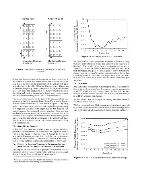
In Figure 13 we show the geometric average of the area-delay<br />
product of the benchmarks vs. cluster size. An important result is<br />
visible in this figure — clusters of size 3 through 20 provide the<br />
best trade-off between area <strong>and</strong> delay, with the best results occurring<br />
for a cluster of size 8. Compared to a cluster of size one, a<br />
cluster of size eight has an area-delay product that is 33.5% less.<br />
7.4 EFFECT OF ROUTING TRANSISTOR SIZING ON CRITICAL<br />
PATH DELAY AND AREA AT VARIOUS CLUSTER SIZES<br />
The purpose of this section is to provide a verification that the<br />
manner in which we sized routing buffers <strong>and</strong> transistors is acceptable,<br />
<strong>and</strong> did not favor one cluster size over another.<br />
1 Changes in delay <strong>and</strong> area due to different size routing buffers is<br />
accounted for in VPRs timing <strong>and</strong> area models.<br />
1<br />
2<br />
A<br />
B<br />
Manhattan Distance<br />
A to B = 2<br />
Area-Delay Product<br />
(Geometric Average Over 20 Circuits)<br />
0.2<br />
0.19<br />
0.18<br />
0.17<br />
0.16<br />
0.15<br />
0.14<br />
We have repeated the experiments described in Section 7 using<br />
transistor <strong>and</strong> buffer sizes of one-half <strong>and</strong> double the sizes used in<br />
Section 7. The results from these experiments are shown in<br />
Figures 14, 15, <strong>and</strong> 16. These experiments show that area can be<br />
traded for speed, <strong>and</strong> speed for area. Figure 16 shows that for large<br />
cluster sizes, our “regular” transistor sizing is too large for the best<br />
area-delay trade-off. Therefore, for large cluster sizes the “half”<br />
transistor size results are a better indicator of the architecture performance.<br />
7.5 SUMMARY<br />
0.13<br />
0 2 4 6 8 10 12 14 16 18 20<br />
Cluster Size<br />
Figure 13 Area-Delay Product vs. Cluster Size<br />
Any architecture with clusters in the range of size 3 to 20 is reasonable,<br />
with size 8 being the best. On average, circuits implemented<br />
in an FPGA with size eight clusters have 23% less delay (a 30%<br />
increase in speed) <strong>and</strong> use 14% less area than circuits implemented<br />
in an FPGA with size one clusters.<br />
We also showed how the sizing of the routing transistors <strong>and</strong> buffers<br />
affects area <strong>and</strong> delay.<br />
While we presented only 20 circuit average results in this paper, all<br />
of the individual benchmark circuits tracked these averages quite<br />
well (with minor variations, mostly at cluster sizes one <strong>and</strong> two).<br />
Minimum-Width Transistor Areas<br />
(Geometric Average Over 20 Circuits)<br />
7e+06<br />
6e+06<br />
5e+06<br />
4e+06<br />
3e+06<br />
2e+06<br />
1e+06<br />
Regular Transistor Size<br />
Half Transistor Size<br />
Double Transistor Size<br />
0<br />
0 2 4 6 8 10 12 14 16 18 20<br />
Cluster Size<br />
Figure 14 Area vs. Cluster Size for Various Transistor Sizings


