

Alexander (Sandy) Marquardt, Vaughn Betz, and Jonathan Rose
Alexander (Sandy) Marquardt, Vaughn Betz, and Jonathan Rose
Alexander (Sandy) Marquardt, Vaughn Betz, and Jonathan Rose

Create successful ePaper yourself
Turn your PDF publications into a flip-book with our unique Google optimized e-Paper software.
Number of Cluster Inputs (I)<br />
(20 Benchmark Average)<br />
45<br />
40<br />
35<br />
30<br />
25<br />
20<br />
15<br />
10<br />
5<br />
T-Vpack<br />
Vpack<br />
0<br />
0 2 4 6 8 10 12 14 16 18 20<br />
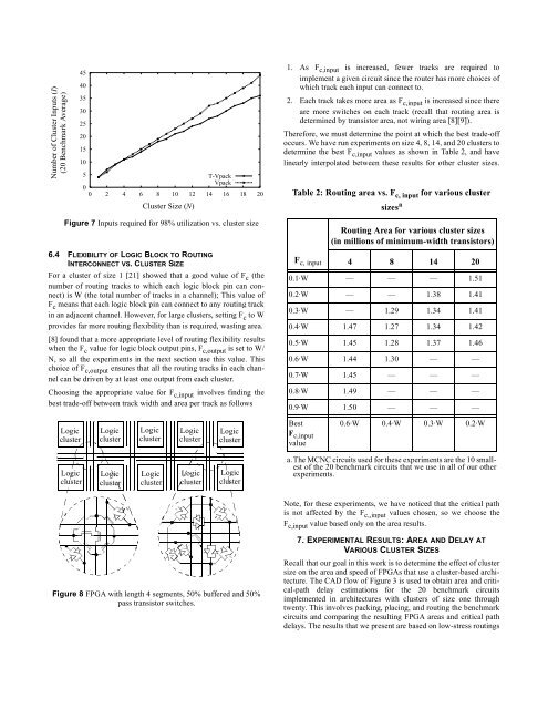
Figure 7 Inputs required for 98% utilization vs. cluster size<br />
6.4 FLEXIBILITY OF LOGIC BLOCK TO ROUTING<br />
INTERCONNECT VS. CLUSTER SIZE<br />
For a cluster of size 1 [21] showed that a good value of F c (the<br />
number of routing tracks to which each logic block pin can connect)<br />
is W (the total number of tracks in a channel); This value of<br />
F c means that each logic block pin can connect to any routing track<br />
in an adjacent channel. However, for large clusters, setting F c to W<br />
provides far more routing flexibility than is required, wasting area.<br />
[8] found that a more appropriate level of routing flexibility results<br />
when the F c value for logic block output pins, F c,output is set to W/<br />
N, so all the experiments in the next section use this value. This<br />
choice of F c,output ensures that all the routing tracks in each channel<br />
can be driven by at least one output from each cluster.<br />
Choosing the appropriate value for F c,input involves finding the<br />
best trade-off between track width <strong>and</strong> area per track as follows<br />
Logic<br />
cluster<br />
Logic<br />
cluster<br />
Logic<br />
cluster<br />
Logic<br />
cluster<br />
Cluster Size (N)<br />
Logic<br />
cluster<br />
Logic<br />
cluster<br />
Logic<br />
cluster<br />
Logic<br />
cluster<br />
Logic<br />
cluster<br />
Logic<br />
cluster<br />
Figure 8 FPGA with length 4 segments, 50% buffered <strong>and</strong> 50%<br />
pass transistor switches.<br />
1. As F c,input is increased, fewer tracks are required to<br />
implement a given circuit since the router has more choices of<br />
which track each input can connect to.<br />
2. Each track takes more area as F c,input is increased since there<br />
are more switches on each track (recall that routing area is<br />
determined by transistor area, not wiring area [8][9]).<br />
Therefore, we must determine the point at which the best trade-off<br />
occurs. We have run experiments on size 4, 8, 14, <strong>and</strong> 20 clusters to<br />
determine the best F c,input values as shown in Table 2, <strong>and</strong> have<br />
linearly interpolated between these results for other cluster sizes.<br />
Table 2: Routing area vs. F c, input for various cluster<br />
F c, input<br />
sizes a<br />
Routing Area for various cluster sizes<br />
(in millions of minimum-width transistors)<br />
4 8 14 20<br />
0.1·W — — — 1.51<br />
0.2·W — — 1.38 1.41<br />
0.3·W — 1.29 1.34 1.41<br />
0.4·W 1.47 1.27 1.34 1.42<br />
0.5·W 1.45 1.28 1.37 1.46<br />
0.6·W 1.44 1.30 — —<br />
0.7·W 1.45 — — —<br />
0.8·W 1.49 — — —<br />
0.9·W 1.50 — — —<br />
Best<br />
F c,input<br />
value<br />
0.6·W 0.4·W 0.3·W 0.2·W<br />
a.The MCNC circuits used for these experiments are the 10 smallest<br />
of the 20 benchmark circuits that we use in all of our other<br />
experiments.<br />
Note, for these experiments, we have noticed that the critical path<br />
is not affected by the F c,,input values chosen, so we choose the<br />
F c,input value based only on the area results.<br />
7. EXPERIMENTAL RESULTS: AREA AND DELAY AT<br />
VARIOUS CLUSTER SIZES<br />
Recall that our goal in this work is to determine the effect of cluster<br />
size on the area <strong>and</strong> speed of FPGAs that use a cluster-based architecture.<br />
The CAD flow of Figure 3 is used to obtain area <strong>and</strong> critical-path<br />
delay estimations for the 20 benchmark circuits<br />
implemented in architectures with clusters of size one through<br />
twenty. This involves packing, placing, <strong>and</strong> routing the benchmark<br />
circuits <strong>and</strong> comparing the resulting FPGA areas <strong>and</strong> critical path<br />
delays. The results that we present are based on low-stress routings


