ZTE Communications
ZTE Communications
ZTE Communications

You also want an ePaper? Increase the reach of your titles
YUMPU automatically turns print PDFs into web optimized ePapers that Google loves.
Multi-Carrier Source<br />
•<br />
•<br />
•<br />
•<br />
•<br />
•<br />
TX1<br />
Data 1<br />
TX2<br />
Data 2<br />
TX3<br />
Data 3<br />
Optical<br />
Filter<br />
Optical<br />
Filter<br />
Optical<br />
Filter<br />
S pecial Topic<br />
Super-Receiver Design for Superchannel Coherent Optical Systems<br />
Cheng Liu, Jie Pan, Thomas Detwiler, Andrew Stark, Yu-Ting Hsueh, Gee-Kung Chang, and Stephen E. Ralph<br />
Multiplexer<br />
Channel<br />
123<br />
DSP: digital signal processor LO: local oscillator<br />
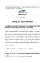
as at the transmitter side. The synchronized information<br />
across the channels is captured for future joint signal<br />
processing. For this reason, the optical path and electrical<br />
path of each demultiplexed channel need to be equal in<br />
length, and digital sampling must be synchronized across the<br />
channels. However, these requirements can be relaxed in a<br />
joint DSP block if time-domain memory size is increased (Fig.<br />
2). In a joint DSP block, information is available from multiple<br />
channels, and this enables joint signal processing to<br />
compensate for both linear and nonlinear impairments<br />
between channels. This also enables joint carrier phase<br />
recovery in carrier-locked Nyquist WDM systems.<br />
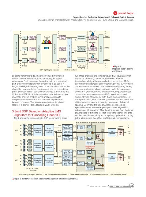
3 Joint DSP Based on Adaptive LMS<br />
Algorithm for Cancelling Linear ICI<br />
Fig. 2 shows the proposed joint DSP for cancelling linear<br />
Ch1<br />
Ch2<br />
Ch3<br />
λ1<br />
λ2<br />
λ3<br />
XI<br />
XQ<br />
YI<br />
YQ<br />
XI<br />
XQ<br />
YI<br />
YQ<br />
XI<br />
XQ<br />
YI<br />
YQ<br />
ADC<br />
ADC<br />
ADC<br />
ADC<br />
ADC<br />
ADC<br />
ADC<br />
ADC<br />
ADC<br />
ADC<br />
ADC<br />
ADC<br />
Synchronized<br />
Sampling<br />
Chromatic<br />
Dispersion<br />
Equalizer<br />
Chromatic<br />
Dispersion<br />
Equalizer<br />
Chromatic<br />
Dispersion<br />
Equalizer<br />
CMA<br />
Polarization<br />
DEMUX<br />
CMA<br />
Polarization<br />
DEMUX<br />
CMA<br />
Polarization<br />
DEMUX<br />
Demultiplexer<br />
•<br />
•<br />
•<br />
•<br />
•<br />
•<br />
Optical<br />
Filter<br />
Optical<br />
Filter<br />
Optical<br />
Filter<br />
Multi-Carrier LO Source<br />
Timing &<br />
Carrier Phase<br />
Recovery<br />
Timing &<br />
Carrier Phase<br />
Recovery<br />
Timing &<br />
Carrier Phase<br />
Recovery<br />
λ1<br />
λ2<br />
λ3<br />
Coherent<br />
Receiver 1<br />
Coherent<br />
Receiver 2<br />
Coherent<br />
Receiver 3<br />
Synchronized<br />
Sampling<br />
Channel 1<br />
Electrical<br />
Filter<br />
Channel 2<br />
Electrical<br />
Filter<br />
Channel 3<br />
Electrical<br />
Filter<br />
Joint DSP<br />
•<br />
•<br />
•<br />
Data 1<br />
Data 2<br />
Data 3<br />
•<br />
•<br />
•<br />
◀Figure 1.<br />
Proposed super-receiver<br />
architecture.<br />
ICI. Three channels are considered, and ICI equalization for<br />
the center channel (channel two) is shown. After the<br />
three-channel signal is sampled with synchronized ADCs,<br />
each channel undergoes conventional DSP, that is, chromatic<br />
dispersion compensation, polarization demultiplexing, timing<br />
recovery, and carrier phase estimation. After timing recovery<br />
and carrier phase recovery, an adaptive ICI equalizer based<br />
on adaptive least mean square (LMS) algorithm is used<br />
across all three channels for both X and Y polarizations. For<br />
each polarization, side channels (channels one and three) are<br />
shifted in the frequency domain by the amount of channel<br />
spacing. By shifting the side channels into the original<br />
spectral location, the overlapped spectra are aligned for<br />
subsequent ICI equalizer. After then the signals from the three<br />
channels are fed into the ICI filter, where the filter coefficients<br />
W12, W22, and W32 are jointly and adaptively updated according<br />
to the slicing error. Each filter coefficient Wij represents the<br />
ADC: analog-to-digital converter CMA: constant modulus algorithm ICI: interchannel interference ISI: intersymbol interference LMS: least mean square<br />
▲Figure 2. Joint DSP based on adaptive LMS algorithm for cancelling linear ICI.<br />
XPol<br />
XPol<br />
XPol<br />
YPol<br />
YPol<br />
YPol<br />
Timing &<br />
Carrier Phase<br />
Recovery<br />
Timing &<br />
Carrier Phase<br />
Recovery<br />
Timing &<br />
Carrier Phase<br />
Recovery<br />
Ch1<br />
Ch2<br />
Ch3<br />
Ch1<br />
Ch2<br />
Ch3<br />
Freq.<br />
Shift<br />
Freq.<br />
Shift<br />
Freq.<br />
Shift<br />
Freq.<br />
Shift<br />
W12<br />
W22<br />
W32<br />
Adaptive<br />
Update<br />
Adaptive LMS<br />
ICI Equalizer<br />
W12<br />
W22<br />
W32<br />
Adaptive<br />
Update<br />
Ch2<br />
XPol<br />
+ -<br />
+ -<br />
e<br />
Ch2<br />
YPol<br />
e<br />
ISI<br />
Equalizer<br />
ISI<br />
Equalizer<br />
Symbol<br />
Detection<br />
Symbol<br />
Detection<br />
•<br />
•<br />
•<br />
Ch2<br />
XPol<br />
Ch2<br />
YPol<br />
•<br />
•<br />
•<br />
March 2012 Vol.10 No.1 <strong>ZTE</strong> COMMUNICATIONS 31