ZTE Communications
ZTE Communications
ZTE Communications

You also want an ePaper? Increase the reach of your titles
YUMPU automatically turns print PDFs into web optimized ePapers that Google loves.
R esearch Papers<br />
Hardware Architecture of Polyphase Filter Banks Performing Embedded Resampling for Software-Defined Radio Front-Ends<br />
Mehmood Awan, Yannick Le Moullec, Peter Koch, and Fred Harris<br />
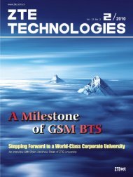
▼Table 1. Resource complexities and required process clock rates for<br />
an M -path polyphase filter with P1-P5 polyphase structures (with fs as<br />
the input rate)<br />
P1<br />
P2<br />
P3<br />
P4<br />
P5<br />
Mults<br />
N<br />
N<br />
2<br />
N<br />
2<br />
1<br />
N<br />
M<br />
Adds<br />
N ( -1<br />
M ) M<br />
( ) M<br />
N ( -1<br />
M ) M<br />
N<br />
M -1<br />
1<br />
2<br />
Regs<br />
N<br />
N<br />
2N<br />
N +1<br />
N +2(<br />
N<br />
M )<br />
Mux<br />
N -( )<br />
N M<br />
N -( 2<br />
)<br />
( )<br />
N<br />
f S<br />
( M)<br />
f S<br />
2(<br />
M)<br />
f S<br />
2(<br />
M)<br />
N<br />
( f S M<br />
) f S<br />
control sequence so that the data registers and coefficients of<br />
the desired subfilter can be selected to perform MAC<br />
operations. The MAC operations can be performed in parallel<br />
or in serial so that a serial polyphase structure with parallel<br />
MAC (Fig. 1d) or serial MAC (Fig. 1e) is formed [7].<br />
Table 1 shows the resource complexity in an M-path<br />
polyphase filter (each path with N/M taps) for a general<br />
polyphase structure (P1), symmetric structure (P2),<br />
adder-shared symmetric structure (P3), and serial polyphase<br />
structure with serial MAC (P4) and parallel MAC (P5). It also<br />
shows the required operating clock rates for these structures<br />
(with fs as the input rate). There is a trade-off between<br />
complexities and processing clock rates. A serial polyphase<br />
filter with serial MAC has the least complexity but demands a<br />
high clock rate. A serial polyphase filter with parallel MAC has<br />
a slightly higher complexity and operates at a clock rate that<br />
corresponds to the input clock rate. Among all the solutions<br />
which do not operate at a clock rate higher than the input<br />
clock rate, the P5 uses the least resources.<br />
A non-maximally decimated polyphase filter bank<br />
processes M subfilters in a time period which is either less or<br />
greater than the M data-load’s time period. The embedded<br />
resampling in the polyphase filter banks requires architectural<br />
changes for the structures (Fig. 1) to meet the output time<br />
constraint. These changes mainly apply to the structures<br />
which are sharing resources (P2, P3, P4 and P5). P1 is a fully<br />
parallel solution and is not operationally affected in<br />
non-maximally decimated modes because each subfilter is<br />
operating independently and M subfilters can be processed<br />
even for a single data input time period. However, it does<br />
require some changes in its state machine. Symmetric<br />
structures are limited to cases with an even number of<br />
polyphase partitions to make use of filter symmetry which is<br />
not the case for serial polyphase structures. Here, we<br />
describe the mapping of P5 onto the target platform—a Xilinx<br />
Virtex-5 FPGA (xc5vsx50t-3ff1136) [8]. A fixed-point<br />
analysis has been used to determine the word lengths that<br />
keep quantization errors below 60 dB (commonly required).<br />
There are a number of design options that correspond to<br />
the level of FPGA resource exploitation. The targeted<br />
polyphase filter used for the embedded resampling cases [3]<br />
has five paths each with six taps. A straightforward mapping<br />
of the corresponding P5 structure onto an FPGA, where all the<br />
56<br />
N<br />
( M ) -1<br />
<strong>ZTE</strong> COMMUNICATIONS<br />
0<br />
0<br />
N<br />
M +1<br />
N<br />
M<br />
Demux<br />
0<br />
0<br />
M<br />
2<br />
March 2012 Vol.10 No.1<br />
0<br />
0<br />
Process Clock rate<br />
f S<br />
filter coefficients and the subfilters’tapped delay lines are<br />
implemented as combination logic blocks (CLBs), results in<br />
relatively high usage of slice registers and LUTs. The<br />
implementation scales linearly with the filter size. Today’s<br />
FPGAs have rich architectures with special memory resources<br />
such as distributed RAM and block RAM, high-performance<br />
computational resources such as DSP48E slices in addition to<br />
the basic CLBs. The DSP48E slice improves flexibility,<br />
utilization, and efficiency of applications. It also reduces<br />
overall power consumption, increases maximum frequency,<br />
and reduces setup and clock-to-out time [9]. The efficient<br />
use of these dedicated resources creates a<br />
high-performance system with high operating clock rates and<br />
reduced CLB requirements.<br />
The filter coefficient bank can be easily replaced by FPGA<br />
block RAMs to eliminate the number of CLB resources;<br />
however, the polyphase-partitioned data bank (register bank)<br />
is a bit critical because it has to shift the new data element to<br />
the respective subfilter’s tap-delay line and having access to<br />
all the taps of that subfilter at the same time. In a maximally<br />
decimated system, where the down-sampling factor is equal<br />
to the polyphase partition, a first-in first-out (FIFO) can be<br />
used as delay lines to derive the optimal architecture, as<br />
described in [9]. For non-maximally decimated systems, a<br />
two-dimensional memory solution is required in which only<br />
the targeted subfilter can be loaded with the input data. Fig. 2<br />
shows the resource usage when mapping a 5 × 6 register<br />
bank (with 32-bit complex data) according to different design<br />
options available on the Virtex-5 FPGA. The 5 × 6 register<br />
bank based on slice registers and LUTs uses 960 slice<br />
registers and 389 LUTs. Each data register in the subfilters is<br />
replaced with a RAM-based shift register (SRL16 / SRL32<br />
mode of the slice LUTs), and the number of slice registers and<br />
LUTs usage becomes 0 and 389, respectively. This eliminates<br />
the need for slice registers, but the LUT usage remains<br />
unchanged. In Virtex-5, each CLB has 64-bit distributed<br />
RAM [8] that is bit-addressable. For a 32-bit data register,<br />
32 CLBs are collectively used as a single 32-bit register. The<br />
remaining 63 bits in each CLB are unused. Distributed<br />
memory is used so that each 64-bit memory contributes one<br />
bit to a 32-bit data register for 64 subfilters (only five are<br />
used). In this way, the memory that was previously used for<br />
only one data register of a subfilter is now used for one data<br />
register for all five subfilters. The resource usage for a 5 × 6<br />
register bank based on distributed RAM becomes 192 slice<br />
registers and 192 LUTs. This eliminates the need for the<br />
decoder and multiplexers to select the desired subfilter’s<br />
data elements in the case of a shift-register-based register<br />
bank. The same concept can be applied to block RAM, which<br />
eliminates CLB usage. Three block RAMs are used for a 5 × 6<br />
register bank, which corresponds to 2% utilization of block<br />
RAM resources for a Virtex-5.<br />
To use block RAM-based register banks, an extra clock<br />
cycle is needed for each data load and shift [10] because six<br />
block RAMs (32-bit × 5) are cascaded to form a 5 × 6 register<br />
bank, and the data shift in the subfilters requires data to be<br />
available from the preceding memory. Therefore, one clock