ZTE Communications
ZTE Communications
ZTE Communications

You also want an ePaper? Increase the reach of your titles
YUMPU automatically turns print PDFs into web optimized ePapers that Google loves.
I(t)<br />
Q(t)<br />
A/D<br />
A/D<br />
FFE: feed-forward equalizer<br />
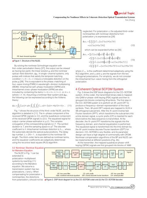
▲Figure 1. Structure of the NLEE.<br />
By solving the nonlinear Schrödinger equation with<br />
first-order perturbation theory [27], the output can be viewed<br />
as having two parts: the linear solution μn and the nonlinear<br />
optical-field distortion, Δμn. In single-channel systems, only<br />
pulses with indices that satisfy the temporal matching<br />
condition l + m - k = n induce a noticeable distortion on the<br />
pulse μn[28]. This is equivalent to the phase-matching of<br />
four-wave mixing (FWM) in wavelength-division multiplexing<br />
(WDM). Intrachannel self-phase modulation (ISPM) and<br />
intrachannel cross-phase modulation (IXPM) are also<br />
included by containing the items l = m = k = n, l = n , or m = n<br />
(where l ≠ m). Assuming a nonlinear fiber system and Δμn,<br />
the following can be expressed according to the Volterra<br />
theory:<br />
N<br />
Fig. 1 shows the structure of the third-order NLEE, and the<br />
algorithm is detailed in [11]. The in-phase component of the<br />
received QPSK signals is I (t ), and the quadrature component<br />
of the received QPSK signals is Q (t ). The equalized signal for<br />
output-carrier phase estimation is ye(t ). The complex<br />
conjugation of the corresponding signals is ( )*. The symbol<br />
duration is T, and the sampling space is qT. The discrete<br />
coefficient is h. Intrachannel nonlinear distortion is hl,m,k , where<br />
the subscripts denote the optical pulse positions. The delay<br />
tap number, L = 2N + 1 , is equivalent to the nonlinear ISI<br />
length. The third-order items are defined as nonlinear terms,<br />
and the equalizer coefficients are adaptively determined<br />
using the recursive least square (RLS) algorithm.<br />
3.2 Nonlinear Electrical Equalizer<br />
for Manakov Equation<br />
The NLEE in Fig. 1 can be<br />
extended to<br />
polarization-multiplexed<br />
systems by rewriting (11)<br />
according to the Manakov<br />
equation. We assume a<br />
transmission system has two<br />
polarizations, x and y. When<br />
compensating for polarization x<br />
nonlinearities, the distortions<br />
from polarization y should not be<br />
j<br />
yr(t )<br />
• ••<br />
0* 0*<br />
• •<br />
q T • q T<br />
•<br />
… …<br />
h 0 h 001 h 1 h 012 h 122 h 2<br />
+<br />
FFE<br />
••<br />
0*<br />
•<br />
ye(t )<br />
Δun =∑CpuP(n-p)+∑ ∑ ∑Cl,m,ku(n-l)u(n-m)u*(n-k )+... (11)<br />
P =-N<br />
N<br />
N<br />
N<br />
I =-N m =I k =m<br />
Data<br />
Data<br />
QAM or<br />
PSK<br />
De-Mapping<br />
QAM or<br />
PSK<br />
Mapping<br />
P/S NLEE<br />
S/P<br />
Slicer<br />
Clock<br />
Phase<br />
Correction<br />
LPF: low-pass filter<br />
NLEE: nonlinear electrical equalizer<br />
neglected. For polarization x, the adjusted third-order<br />
nonlinearities with nonlinear distortions from<br />
polarization y is expressed as [29]<br />
which can be expanded further as [30]<br />
where C l,m,k is the coefficient determined adaptively using the<br />
RLS algorithm, and ux and uy are the signals from the two<br />
orthogonal polarizations. For simplicity, we do not consider<br />
the intrachannel four-wave mixing from the orthogonal<br />
polarization.<br />
4 Coherent Optical SCFDM System<br />
Fig. 2 shows the DSP block diagrams for the CO-SCFDM<br />
system. At the coder, the transmitted binary data is mapped<br />
into QAM or phase-shift keying (PSK) signals and then is<br />
grouped into blocks containing M symbols. The first step in<br />
the CO-SCFDM system is to perform an M -point DFT to<br />
produce a frequency-domain representation of the input<br />
symbols. Then, M-point DFT outputs are mapped to N (N ≥<br />
M) orthogonal subcarriers. After the N-point inverse fast<br />
Fourier transform (IFFT), which transforms the subcarriers into<br />
a time domain signal, a cyclic prefix (CP) is inserted for each<br />
block before the data sequence is transmitted. At the<br />
decoder, the N -point FFT transforms the signals into the<br />
frequency domain, and channel equalization is performed.<br />
The equalized signal is transformed into the time domain by<br />
the M -point inverse discrete Fourier transform (IDFT) for<br />
decision. CO-SCFDM is very flexible, and its parameter<br />
design can have a high degree of commonality with OFDM.<br />
Nonlinear compensation algorithms of the BP and NLEE can<br />
be implemented at different positions (Fig. 2b).<br />
At the transmitter, the mapped quadrature phase-shift<br />
keying (QPSK) signals are first grouped into blocks of 1680<br />
M-Point<br />
DFT<br />
M-Point<br />
IDFT<br />
Δux,n =∑∑∑C l,m,k[ux(l )ux(m)uz*(k )<br />
Subcarrier<br />
Mapping<br />
l m k<br />
+ux (l )uy(m)uy*(k )] (12)<br />
Δu x,n =∑Cl [ux (l)( ux(l) 2 + uy(l ) 2 )]<br />
l<br />
+∑∑Cm,l[ux(l ) ( ux(m) 2 + uy (m) 2 )]<br />
N-Point<br />
IFFT<br />
Equalization N-Point<br />
FFT<br />
Remove<br />
CP<br />
CP: cyclic prefix<br />
IDFT: inverse discrete Fourier transform<br />
Back<br />
Propagation<br />
S/P LPF<br />
LPF: low-pass filter<br />
S/P: serial/parallel<br />
▲Figure 2. DSP block diagram for (a) the CO-SCFDM coder and (b) the CO-SCFDM decoder.<br />
(a)<br />
(b)<br />
l m<br />
+∑∑Cl,m[ux(m)( ux(l ) 2 +ux (l )uy(m)uy*(l ) ]<br />
l m<br />
+∑∑∑C l,m,k [ux (l )ux(m)ux*(k )+ux(l )uy(m)uy*(k )<br />
l m k<br />
P/S<br />
Add<br />
CP<br />
S pecial Topic<br />
Compensating for Nonlinear Effects in Coherent-Detection Optical Transmission Systems<br />
Fan Zhang<br />
LPF<br />
(13)<br />
Transmitted<br />
Signal<br />
Received<br />
Signal<br />
March 2012 Vol.10 No.1 <strong>ZTE</strong> COMMUNICATIONS 47