Capturing CO2 from ambient air - David Keith
Capturing CO2 from ambient air - David Keith
Capturing CO2 from ambient air - David Keith

Create successful ePaper yourself
Turn your PDF publications into a flip-book with our unique Google optimized e-Paper software.
The reactive surface area during trials in the prototype cannot be precisely known, but we can makes estimates<br />
using available information about nozzles, flow rates, and other parameters. Using our experimental<br />
data with these estimates we calculate values of kspray of 1–3×10 −3 . The range is <strong>from</strong> the low molarity<br />
solution to the high molarity solution, as expected. We may note by comparison with Equation 3.3, that<br />
theoretically:<br />
kspray,theory = C0�<br />
Dlk[OH<br />
C<br />
− ]<br />
Calculated values of kspray using this equation are about twice those calculated <strong>from</strong> data, reflecting that<br />
absorption in the contactor was about half of what was expected <strong>from</strong> theory and available drop size<br />
information. The discrepancy may be due to some mechanistic inefficiency in mass transfer, less-thanexpected<br />
drop surface area, or some other effect. We will use the highest empirical value in the cost<br />
calculations.<br />
We approximate S as uniform with height (this is not strictly accurate, but the distribution of S will not<br />
affect the average mass transfer significantly), so that Equation 3.14 can be integrated to yield:<br />
C = Cine −Sksprayt<br />
To get the outlet concentration, Cout, we evaluate this at t = H<br />
v<strong>air</strong> :<br />
The rate of <strong>CO2</strong> capture of the contactor (denoted ˙M) is then:<br />
3.4.2 Capital cost<br />
Cout = Cine −SksprayH/v<strong>air</strong> (3.15)<br />
˙M = (Cin −Cout) · v<strong>air</strong> · A = Cin(1 − e −SksprayH/v<strong>air</strong> ) · v<strong>air</strong> · A (3.16)<br />
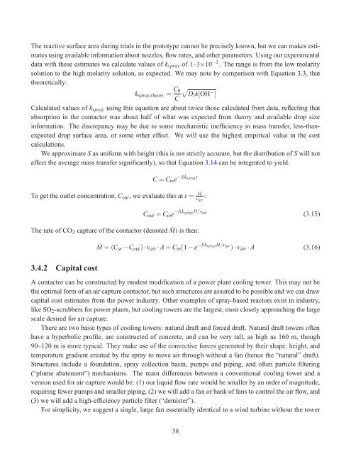
A contactor can be constructed by modest modification of a power plant cooling tower. This may not be<br />
the optimal form of an <strong>air</strong> capture contactor, but such structures are assured to be possible and we can draw<br />
capital cost estimates <strong>from</strong> the power industry. Other examples of spray-based reactors exist in industry,<br />
like SO2-scrubbers for power plants, but cooling towers are the largest, most closely approaching the large<br />
scale desired for <strong>air</strong> capture.<br />
There are two basic types of cooling towers: natural draft and forced draft. Natural draft towers often<br />
have a hyperbolic profile, are constructed of concrete, and can be very tall, as high as 160 m, though<br />
90–120 m is more typical. They make use of the convective forces generated by their shape, height, and<br />
temperature gradient created by the spray to move <strong>air</strong> through without a fan (hence the “natural” draft).<br />
Structures include a foundation, spray collection basin, pumps and piping, and often particle filtering<br />
(“plume abatement”) mechanisms. The main differences between a conventional cooling tower and a<br />
version used for <strong>air</strong> capture would be: (1) our liquid flow rate would be smaller by an order of magnitude,<br />
requiring fewer pumps and smaller piping, (2) we will add a fan or bank of fans to control the <strong>air</strong> flow, and<br />
(3) we will add a high-efficiency particle filter (“demister”).<br />
For simplicity, we suggest a single, large fan essentially identical to a wind turbine without the tower<br />
38