


Create successful ePaper yourself
Turn your PDF publications into a flip-book with our unique Google optimized e-Paper software.
udderpost.<br />
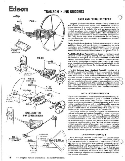
FIG 613<br />
Outboard Lever<br />
Quadrant<br />
-<br />
FIG 814<br />
TRANSOM HUNG RUDDERS<br />
A = 23"<br />
57.5 cm Assembly weight 39.8 lbs117.9K<br />
adiustable I or to suit<br />
CABLE SYSTEM<br />
FOR DOUBLE ENDER<br />
/<br />
5"112 cm<br />
(min.)<br />
minimum -<br />
I .- .<br />
Quadrant<br />
8 For complete waranty information - see inside front cover.<br />
ny<br />
RACK AND PINION STEERERS id RACK AND PINION STEERERS<br />
Designed specifically for double ended boats up to about 38'<br />
with transom hung rudders. Edson's new model Rack and Pinion<br />
Steerer operates in a similar fashion to the standard Rack and<br />
Pinion Steerer with the feel of a tiller and very responsive to the<br />
touch. It is available in two models: for straight in-line installations<br />
on vertical or nearly verticle rudders and for offset installations, re-<br />
quiring a shaft universal and an adjustable bearing for angled rud-<br />
ders. They require only a small slot in the stern for the operating<br />
rod. This slot can be easily sealed with a homemade boot similar to<br />
one for a mast step.<br />
Fig.814 Double Ender Rack and Pinion Steerer consists of a Rack<br />
and Pinion Steerer with lever, 2 clevis units, connecting rod and-a<br />
rudder lever unit. The geared quadrant is designed to mount on a<br />
1-112"13.8cm dummy rudderpost. The ''A" dimension is 21 ", theUC"<br />
dimension is 16" or either is available to suit. Weight 46 lbs.120.7k.<br />
Fig. 815 Double Ender Rack and Pinion Steerer complete with shaft<br />
universal and 1" self-aligning bearing. This <strong>steerer</strong> is the same<br />
basic model as the Fig 814, but it incorporates a shaft universal and<br />
bearina. This Divots at a ~oint 14-112"forward of the dummv rudderpost.<br />
The self'aligning bearing is then placed forward of tie universal<br />
as close to the wheel as possible to keep the wheel with a solid<br />
feel. The universal can change the shaft angle up to 30 degrees.<br />
Weight 49 lbs.122.lk.<br />
Fig. 613 Outboard Lever Quadrant Assembly consists of a<br />
12"/30.5cm quadrant (Fig. 668) 2 clevis units, connecting rod, and<br />
rudder lever unit. This assembly is designed for double ended<br />
boats which want to use a roller chain type <strong>steerer</strong> (ie Pedestal,<br />
Bulkhead Steerer, or Geared Reduction Steerer) in conjunctionwith<br />
an outboard rudder quadrant. The steering cables can be ledj #)<br />
aft from your choice of <strong>steerer</strong>s using an appropriate combination -'.<br />
of sheaves or ~ull-~ull conduit. The quadrant is desianed to mount<br />
on a 1 112" 13.8cm dummy rudderpost. For ordering &d installation<br />
instructions, refer to the double ended rack & pinion <strong>steerer</strong> below.<br />
INSTALLATION INFORMATION<br />
First of all it is important to establish and install the reinforced plat-<br />
form that the dummy rudderpost is going to be bolted to. Bear in<br />
mind that this surface must be of sufficient strength as it must<br />
absorb all of the steering loads. This platform must be 90" to the<br />
rudder on a plane where you wish to install the rudder lever. Also<br />
note that the geared rack and pinion quadrant requires a minimum<br />
of 10" on each side of the dummy rudderpost to swing in. This<br />
dimension will help in establishing the "C" dimensions.<br />
Temporarily mount the dummy rudderpost and assemble the<br />
rack and pinion gear and housing. Assemble the clevis, the connec-<br />
ting rod, and the rudder lever unit. With 'C' clamps, attach the<br />
rudder lever unit to the rudder. Now operate the <strong>steerer</strong> noting the<br />
rudder travel from side to side. The location of the lever on the rud-<br />
der, either fore or aft or possibly even shimmed to starboard, deter-<br />
mines equal travel from side to side. Take time with the positioning<br />
of this lever and be precise. When you are satisfied, secure all parts<br />
and install stops, such as wooden blocks on each side of <strong>steerer</strong> to<br />
limit its travel to the desired arc. Provisions for an emergency tiller<br />
should now be made if you do not already have one.<br />
ORDERING INFORMATION<br />
-<br />
When ordering a Rack and Pinion Steerer for a double ender,<br />
please specify the figure number, 'A' & 'C' dimensions, type o<br />
boat, and a description of the location of the dummy rudderposj3,<br />
with dimensions. Unless otherwise specified, the geared quadrant '"<br />
will be bored with a 1-112" dummy rudderpost. Refer to ordering information<br />
for Rack and Pinion Steerers for more detailed considerations<br />
when determining the 'A' dimension. Individual parts<br />
are available, see Fig 616, 808 and 8<strong>36</strong>, Tiller Arms. If you require<br />
further assistance, please do not hesitate to contact the Edson factory<br />
for more information.<br />
The Rack Aft <strong>steerer</strong>s are for those boats with at least 12 inches<br />
of space aft of the rudderpost and limited space forward. The basic<br />
dimension of the gear should be carefully noted as it is important to<br />
place the wheel about 32 inches up from the cockpit sole to allow<br />
the helmsman to steer comfortably.<br />
Fig 343 Aft Mount Rack and Pinion Steerer - size 1 is for use on aft<br />
racked rudderposts 1" to 2-118" diameter with a maximum key of<br />
318" in on the aft side of the rudderpost. If the bore is not specified<br />
the rack will be furnished with a718" pilot hole. The "A" Dimension<br />
on the wheel shaft is standard at 15 inches or is available to suit.<br />
Steerer weight: 30 lbs.113.5 k<br />
)Fig 344 Aft Mount Rack and Pinion Steerer is for use on boats with<br />
Q vertical rudderposts or severly aft raked rudderposts. This <strong>steerer</strong><br />
comes with ashaft universal and two 1 "self aligning bearings.This<br />
<strong>steerer</strong> allows the adjustment of the angle of the steering wheel<br />
within a 30" arc.<br />
AFT MOUNTED RACK AND PINION<br />
- - -?<br />
FIG 344 with universal<br />
Auto-Pilots p - 11-7/8"130.1 crn<br />
Ail Edson Rack and Pinion Steerers -A"= 15"/37.5~~ 9-5/8"/ 24 crn<br />
can have auto pilot sprockets at OR TO & &+G,lR,<br />
tached iust forward of the <strong>steerer</strong><br />
frame. bn the aft mounted rack<br />
models there is a 2 inch shaft extension<br />
aft that an auto pilot can be<br />
attached to also.<br />
-<br />
The New Fig 345 Aft Mount Rack and Pinion Steerers are for use on ~xtenderj(<br />
boats with rudderposts raking forward. Although similar to Fig.<br />
344 in function, the exact location of the shaft universal allows<br />
adjustment of the steering wheel from a position parallel to the<br />
plane of the rudderpost to a more comfortable vertical or aft rake<br />
position.<br />
MAINTENANCE<br />
Maintenance of Rack & Pinion Steerers is minimal and when per-<br />
FIG 675 -..,.<br />
coupling<br />
formed at least oncea month, will provide years of trouble-free performance.<br />
Oil shaft bearingsand hinge joints on Hinged Racks with The Fig 345 Aft Mounted Rack a Pinion<br />
Steerer is ideal for installations<br />
#30 Motor Oil. Usealight application of Fig 827Teflon Lubricant on where the Ruddarpost is either raked<br />
the gear teeth and contact point of the adjusting arm. Universal forward or aft.<br />
joints should be packed in grease and booted. Daily inspection is<br />
recommended.<br />
SHAFT MOUNT BRAKE FIG 783<br />
I - ,I U FIG 345<br />
' '<br />
One of the most popular accessories for wheel <strong>steerer</strong>s, this aluminum and bronze with long lasting brake lining and supplied<br />
brake was designed especially for Rack and Pinion and Worm with brake shaft and shiny black brake handle. Brakeshaft lengths<br />
Steerers. Its dampening action is especially handy on long runs or available are 8"120.5cm, 12"/30.6cm and 14"/<strong>36</strong>cm. Special lengths<br />
when operating under power. Can also be used to hold the boat on are available upon request. When ordering be sure to specify Fig<br />
course under most conditions. As a safety feature the brake can be<br />
overridden by the helmsman. The Brake mounts on the wheel shaft<br />
No., size, Brake Shaft length and Shaft diameter. Wt. 2 Ibs.l.91 k.<br />
against the inside forward wall of the wheel box with the adjusting<br />
knob coming out either side of the box. Brakes are constructed of<br />
Size 1 For 1' diameter wheel<br />
shaft to fit ail Rackand Pmon<br />
FOR SEE PEDESTAL FIG 689 BRAKE,<br />
FOR PARTS<br />
RE-ORDERING ,,,N<br />
Size 1-118 For 1.118' diameter<br />
wheel shafts to fit Super<br />
Simplex Size 00<br />
9


