


Create successful ePaper yourself
Turn your PDF publications into a flip-book with our unique Google optimized e-Paper software.
aS4bn ENGINEERING AND INSTALLATION GUIDE<br />
MIDSHIP COCKPIT STEERING pi<br />
INTRODUCTION Needless to say, both Port and Starboard can be run the - 11<br />
This guide has been prepared to enable the designer,<br />
builder and boat owner in planning out the various<br />
methods of installing a wire steering system in a mid-ship<br />
same - down or to the side. it is all a matter of taking the<br />
best course for the available space and the location of<br />
suitable attaching structures for the sheaves.<br />
cockpit boat. The Auto-Pilot has been attached to a second quadrant<br />
Edson offers two types of wire rope systems for the midship<br />
cockpit boat, the conventional wire system and the<br />
new Pull-Pull Conduit Steering System, ideal for boats up<br />
to 42' in length. Regardless of the type and size of midmounted<br />
on the aft side of the rudder post and in this case<br />
down low. With the separate quadrant the boat has in effect<br />
two steering systems - one automatic one mechanical.<br />
For further Auto-Pilot information see Auto-Pilot section.<br />
ship cockpit boat, the steering system should be thought<br />
out at the time the boat is designed or at least before the<br />
interior is in place. There are virtually no boats that can not<br />
be adapted to a wire system.<br />
Whichever system used, the advantages of a wire system<br />
are many and important. The system is simple; this makes<br />
it excellent for those boats going off-shore or to remote<br />
areas. A roller chain pulls the rudder to one side or the<br />
other. If the wire fails you can rig a new wire. Try that with<br />
other types of <strong>steerer</strong>s. It is in effect a screw, nut and bolt<br />
philosophy of design.<br />
The steering will give the boat a personality. There is feel,<br />
response, flexibility and if you want to settle down, put on<br />
a dampening brake, add a simple mechanical Auto-Pilot.<br />
These will give you the best of all worlds.<br />
PLANNING FOR THE WIRE ROPE SYSTEM<br />
lllustrations 2 and 3 show the most commonly used<br />
method of runnina - the wire in a mid-ship Cockpit Boat.<br />
The wire is run to either the port or starboard side by using<br />
the Edson Fig. 607 Adjustable Idler. This directs the wire<br />
aft a small amount, down a small amount to double<br />
sheaves that are mounted on the aft engine room bulkhead.<br />
Care must be taken to make sure that the wire is clear of<br />
the - aoorooriate .. sail lockers.<br />
8<br />
The wire is then directed aft at a level just under the bunk<br />
top and on the outside of the backs of the drawers in an<br />
area aenerallv considered to be otherwise unusable. In<br />
manvcases the wire is run alona - the exhaust line trunk.<br />
Aft the two sheaves are mounted on a stiffening bulkhead,<br />
one sheave leads the wire directly to the quadrant, the<br />
other sheave across the boat to a sheave and then back to<br />
the auadrant. Care must be taken to make sure that the<br />
When using wire rope and sheaves, we are dealing with a wires are led correctly to give the boat directional rather<br />
series of straight lines or for the sake of visualization, than reverse steering. This installation points to the imstraight<br />
connecting rods.<br />
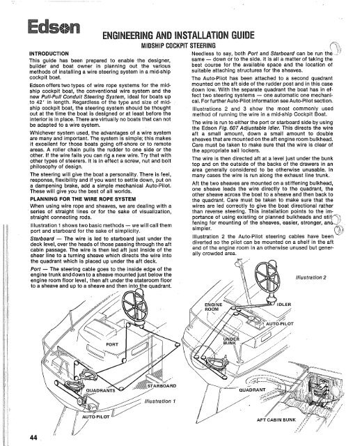
lllustration 1 shows two basic methods - we will call them<br />
port and starboard for the sake of simplicity.<br />
Starboard - The wire is led to starboard just under the<br />
deck level, over the heads of those passing through the aft<br />
cabin passage. The wire is then led aft just inside of the<br />
sheer line to a turning sheave which directs the wire into<br />
portance of using existing or planned bulkheads and stifi6;<br />
fening for mounting of the sheaves, easier, stronger, ana,i<br />
,h<br />
simpler.<br />
( 4 11<br />
lllustration 2 the Auto-Pilot steering cables have been -<br />
diverted so the pilot can be mounted on a shelf in the aft<br />
end of the engine room in an otherwise unused but generally<br />
crowded area.<br />
Port - The steering cable goes<br />
engine trunk anddown to a sheav<br />
engine room floor level, then aft<br />
to a sheave and up to a sheave a<br />
lllustra tion 1<br />
Illustration 2<br />
0<br />
ENGIINEERIING AND<br />
lllustration 3 shows another form of placing the Pedestal in<br />
the Mid-Ship Cockpit Boat. The wire is basically led down<br />
and run beneath the aft cabin sole.<br />
The Pedestal can be placed aft in the cockpit with the pos-<br />
sibility of placing the helmsman on a raised seat for better<br />
visibility over the house.<br />
MlDSHlP COCKPIT STEERING (Continued)<br />
lllustration 3<br />
This installation assumes the engine is directly below the<br />
Pedestal and it is necessary to place Fig. 607 Adjustable<br />
Idler under the <strong>pedestal</strong> to direct the wire aft a small<br />
amount. The sheaves at the floor level can be placed on the<br />
very aft end of the engine compartment and they in turn<br />
will lead aft to two sheaves placed on a transverse bulk-<br />
head directly under the aft cabin floor. These in turn direct<br />
the wire aft, up and out to two sheaves mounted on the<br />
'Ounk front bulkheads and then directed into the quadrant.<br />
Emergency steering can be placed on top of the rudder<br />
post by simply removing the aft cushion and by placing a<br />
tiller at this point. Some owners prefer an extension that<br />
goes through the aft deck to allow placing the tiller over<br />
the aft deck house. This is a personal preference, but by all<br />
means have an emergency method of steering.<br />
The lllustration 4 installation is used on boats with<br />
passage ways, toilets or lockers on both sides of the cock-<br />
pit foot well. With this layout one way to steerthe boat is to<br />
run the wires under the floor of the aft stateroom.<br />
The Pedestal can be placed at the point up against the<br />
ridge deck or in the normal aft position in the cockpit. If<br />
laced forward it does allow the helmsman to be protected<br />
Qn poor weather by the dodger. In addition, the engine con-<br />
trols and instrumentation can all be mounted on the aft end<br />
of the house. This can then place all of the wiring in an<br />
easily accessible trunk within the main cabin.<br />
The wire from the <strong>pedestal</strong> goes down and is "Veed" slight-<br />
ly to allow the wires to go to sheaves fastened to the engine<br />
IMSTALWTION GUIDE ds4t.n<br />
for further i n formation please refer<br />
to the "Pull. -Pull"section and the<br />
"How to Inst ~al1"section of the catalog.<br />
stringers. The wire is then directed aft under the floor in<br />
the natural "V" of the hull. Aft to two sheaves which can be<br />
placed on a simple structure and then out and up to two<br />
sheaves and then into the quadrant. Note how the sheaves<br />
can be fastened to existing bunk fronts andlor bulkheads.<br />
Very important to keep costs in line as well as to keep the<br />
structures simple. .<br />
PLANNING FOR THE PULL-PULL SYSTEM<br />
Edson's new Pull-Pull Steering System is ideal for mid-ship<br />
cockpit boats up to about 42' in length. The Pull-Pull Sys-<br />
tem is an alternative to the standard wire rope and sheave<br />
installation. The following illustrations show just a few of<br />
the many uses of Pull-Pull Steering.<br />
lllustration 5 shows a Destroyer Wheel with a Fig. 338 or<br />
410 Steerer mounted in a cockpit moldment. The moldment<br />
houses engine instrumentation and controls while serving<br />
as a table for cockpit entertaining. Since the quadrant is<br />
mounted on the aft side of the rudderpost, the cables are<br />
crossed within this structure for proper steering direc-<br />
tion.<br />
In this case, one cable runs along the port side to the quad-<br />
rant while the other cable runs directly down the starboard<br />
side. With this type installation, the cables can be anchored<br />
to an existing moldment or plywood reinforcement. Here, it<br />
is attached to the plywood reinforcement normally placed<br />
under aft bunks.<br />
lllustration 6 shows the Pedestal installation using the<br />
841 Mounting Plate for attaching the cable. The cable is<br />
routed along the starboard side under a bunk to a Radial<br />
Drive. One wire can run across to a sheave mounted on the<br />
other side and back into a regular quadrant if space does<br />
COMBINATION PULL-PULL CABLE AND SHEAVES<br />
lllustration 7 shows the cable running down, over the<br />
engine, and aft under the cabin sole. With the sharp bends<br />
aft, the system converts to a standard wire rope and sheave<br />
arrangement connected to a quadrant or Radial Drive.


