


Create successful ePaper yourself
Turn your PDF publications into a flip-book with our unique Google optimized e-Paper software.
TRANSOM HUNG RACY & PINION<br />
RACK AND P ON STEERERS<br />
Designed for transom hung rudder, inboard rudder, double ended boats with d+---l"<br />
board rudder, racing and cruising boats to about 40 feet, these <strong>steerer</strong>s offer the<br />
answer for those requiring a compact, powerful and sensitive wheel system for their<br />
craft. Positive response provides the helmsman with complete feel of the rudder.The<br />
transom hung models offer 1.6 turns of the wheel lock to lock in 70" and the inboard<br />
models, 1.8 turns to lock in 80". Easeof installation is primary feature.Transom hung<br />
rudder models attach directly to the rudder through a slot approximately 2"x 6" in<br />
the transom. lnboard rudder models attach to the rudderpost or rudderpost extension<br />
and are available for mounting either fore or aft of the rudderpost.The <strong>steerer</strong> frames<br />
then bolt onto theaft deckorsuitable mounting surface. You need only build asimple<br />
strong combination seat and cover for over the <strong>steerer</strong>. Rack and pinion <strong>steerer</strong>s are<br />
ruggedly constructed of bronzeand bronzealloys with 1" stainless steel wheel shaft<br />
andhardware. ~hese materials were tested and proven for their extra wear resistance,<br />
reliability, and will provide years of trouble free performance.<br />
RACK AND PINION PLANNING<br />
The Edson Rack and Pinion Steerers are made in four different configurations:<br />
transom hung rudder <strong>steerer</strong>s, two different types of inboard rudder <strong>steerer</strong>s and a<br />
I RUDDER THICKNESS CHART I rack and pinion <strong>steerer</strong> for double enders. These <strong>steerer</strong>s mount 90" to the rudder<br />
Size Rudderstock Weight Size Rudderstock Weight<br />
Fig 341 (inches lcm I Ibs. I k Fig 342 inches cm<br />
175 1-314 4.4 24<br />
-- ,I<br />
I I I , , . .<br />
350 1 3-112 18.9 1 28 1 12.7 1 / 350 1 3.112 18.9 1 31 114.0<br />
axis. ~or.boats with forward rakes, or extreme aft rakes on this axis, the <strong>steerer</strong>s<br />
are available with a shaft universal and an additional bearing. Shaft universals can<br />
change wheel rakes to 30 degrees in either direction.<br />
To allow the helmsman to steercomfortabl~, the top of the wheel should be located<br />
about 32"180.2cm up from the cockpit sole. lnall cases keep the seat low enough so<br />
the helmsman's feet are firmly planted on the cockpit floor or other brace. If they are<br />
left dangling the circulation will be cut off and the position becomes uncomfortable.<br />
~oatswith rudderposts located too low in the cockpit can use the Fig 782 rudderpost<br />
extender and Fig 675 coupling to raise the steering assembly to the required<br />
height.<br />
Edson will be glad to assist in the selection of the correct rack and pinion for your<br />
boat. Just send in the top and side view construction drawings of your boat or, if<br />
these are not available, a simple sketch with dimensions and a photograph will<br />
help.<br />
SELECTION GUIDE '-L (<br />
Rack and pinion <strong>steerer</strong>s are in most cases straight forward. The variables a d<br />
"A" or shaft length, rudderstock for transom-hung rudders, rudderpost size for inboard<br />
rudders and wheet angle. Taking these one at a time.<br />
1. The "A" or shaft dimension is the distance from the axis on which the rudder<br />
. . . . . - - - turns to the aft face of the wheel hub. If you intend on buildina a helm seat over the<br />
<strong>steerer</strong>, be sure to add 6 to 8 inches for ieg clearance between the forward edge of<br />
the seat and the wheel. If there is any question, make the shaft a little long as it can<br />
Built in<br />
Helm Seat be made shorter on the job.<br />
2. The width of the rudder or rudderstock dictates the size for transom hung rudder<br />
<strong>steerer</strong>s Fig 341 and Fig 342. If in doubt, get the next wider jaws as you can<br />
always shim the sides of the casting. The jaws on the gear rack are drilled at the<br />
time of installation.<br />
3. The rudder post diameter determines the size of rack and pinion <strong>steerer</strong>s for inboard<br />
rudders. Refer to the size charts for Fig 343, 344, 346 and 347.<br />
4. All models of rack and pinion <strong>steerer</strong>s are available with shaft universals if you<br />
want to raise or lower the wheel angle.<br />
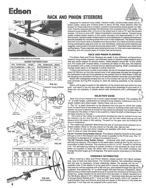
Fig 341 Transom Hung Rudder Steerer. This <strong>steerer</strong> attaches directly to the rudder<br />
through a slot in the transom and the wheel is parallel to the Pintle Line. The "A"<br />
dimension is standard at 21 inches or is available to suit.<br />
Fig 342 Transom Hung Rudder Steerer. Complete with shaft universal and 1"<br />
self-aligning bearing. This <strong>steerer</strong> is the same basic model as the Fig 341, but it in-<br />
FIG 341 corporates a shaft universal. This pivots at a point of 14-112" forward of the Pintle<br />
Line. The self-aligning bearing is placed forward of the universal as close to the<br />
wheel as possible to keep the wheel with a solid feel. The shaft universal can<br />
TRANSOM HUNGRUDDERSTEERERS change the shaft angle up to 30 degrees. The same <strong>steerer</strong> sizes apply to the 342 as<br />
the 341.<br />
6<br />
lL 0 A 1 IL W L I SIX. In Ft L&<br />
Ft -M Ft Inches<br />
to 25 to 22 18 - 20 273 7<br />
26 - 30<br />
31 - <strong>36</strong><br />
23 - 25<br />
26 - 31<br />
20 - 22<br />
22 - 24<br />
300<br />
<strong>36</strong>0<br />
7%<br />
9<br />
2 29<br />
2 7<br />
ORDERING INFORMATION<br />
When ordering a Rack and Pinion Steerer, please specify the Figure number,<br />
size, type of boat and description. For inboard <strong>steerer</strong>s. the rudder~ost diameter<br />
and key size is necessary. Unless otherwise stated, the keyway hill be onquadrant<br />
side. If the <strong>steerer</strong> is to be used with a tubular rudderpost please sd=, ),<br />
vise and you will be supplied with a 318 inch pin, pilot drilled through the cap of thJ quadrant. Also advise the "A" or shaft length that best fits your installation. When<br />
determining a wheel shaft length be sure tb include the thickness of the face of the<br />
wheel box, space needed for an auto-pilot drive sprocket, or length required for a<br />
Fig 783 Brake, (about 2-114"). Wheel shafts are 1 " stainless steel and are machined<br />
to accept Edson Wheels with 1" bore by 2-318" bore length, with a 114" keyway. Inboard<br />
Rudder Rack and Pinions are bored and keyed at the factory if the sizes are<br />
specified. If not they will be supplied with a pilot bore.<br />
"* -<br />
r 21<br />
--<br />
*- \.<br />
'; -1<br />
:tlJ<br />
";"'<br />
The Rack Forward Steerers are for those boats with little or no<br />
room aft of the rudderpost. There are two models, each having dis-<br />
tinctive uses. These should be carefully evaluated.<br />
RACK AND PINION STEERERS -<br />
Fig 347 Forward Mounted Rack and Pinion Steerer. This <strong>steerer</strong><br />
attaches directly to the rudderpost and the wheel is parallel to the<br />
rudder~ost. The "A" on the shaft dimension is standard at 21" or is available<br />
to suit. See chart below for <strong>steerer</strong> sizes.<br />
w-<br />
Rack and Pinion<br />
Fig 346 Forward Mount Rack and Pinion Steerer complete with shaft<br />
universal and a 1" Self-Aligning Bearing. This <strong>steerer</strong> is the same basic<br />
model as the Fig. 347, but it incorporates a shaft universal. This pivots<br />
at a point 141/z1' forward of the rudderpost. The self-aligning bearing is<br />
FIG 346<br />
wlUniversal<br />
INSTALLATION INSTRUCTIONS<br />
Attach the rack to the rudder or rudderpost at a 90" angle. Align the<br />
<strong>steerer</strong> housing on the rack and check to make sure the height and<br />
angle of the wheel shaft are correct. Securely bolt the housing in place<br />
on the aft deck or mounting platform. Make sure this surface has suffiient<br />
strength as it must absorb all of the steering loads. If required,<br />
einforce it. Stops, such as wooden blocks shown to the right, should<br />
-?.<br />
now be installed on both sides of the <strong>steerer</strong> to limit its travel to the<br />
lnboard Rack and Pinion<br />
With Proper I?udder Stops<br />
and Auto-Pilot<br />
Provision for Removable<br />
Emergency Tiller<br />
desired arc. The box over the <strong>steerer</strong> should be waterproof yet. readily<br />
removable. If you intend this box to double as a helmsman seat, be sure<br />
to build it high enough to allow good visibility over the cabin top. Pro- Note: All screws and bolts should be tight, and should be<br />
visions for emergency steering should be made by fitting a removable checked regularly to insure that they remain tight.<br />
tiller on top of the rudder post.<br />
7


