


You also want an ePaper? Increase the reach of your titles
YUMPU automatically turns print PDFs into web optimized ePapers that Google loves.
ds4c.n<br />
AUTO-PILOT STEERING SYSTEMS ./ ..<br />
When planning your steering system it is best to think ahead. Auto-Pilots are more popular than ever and easier to install. Edson nas<br />
developed three basic methods of attaching auto-pilots. first - all Edson Bulkhead Steerers, Rack and Pinion and Worm Steerers can have<br />
auto-pilots attached directly to the wheel shaft extension or the wheel shaft itself -nothing extra to purchase. Second - the use of the<br />
Edson Figure 320 Auto-Pilot Drive with the addition of one or two sheaves and the appropriate roller chain can adapt virtually all Edson<br />
Pedestal Systems to Auto-Pilot attachment. With the 320 the boat can use an extra quadrant or radial drive for a completely separate system<br />
or can introduce the 320 in to the basic wire system. Third - the all new Edson "Rapid Drive" for a right angle gear box drive - the simplest<br />
system for owner, yard, and boat builder.<br />
As a general guide the simpler the system the better. On any installation<br />
involving electricity the area must be well prote~ted from moisture and the<br />
wires used must be of the correct size and used with good solid terminal<br />
ends. At no time can the unit be exposed to salt water such as would occur<br />
if the electrical panel was placed below a sail locker. As obvious as this may<br />
sound we still see many units so mounted. The compass unit must be kept<br />
away from the boat's navigation compass as well as from other interferences<br />
such as an alternator on an engine.<br />
Take the Fig. 320 Pedestal System first. There are two basic concepts that<br />
can be used in the installation of an automatic oilot with a oedestal. One is<br />
to place the Fig. 320~uto-pilot Drive Unit withinthe boat's existing steering<br />
system. This would be as in illustrations 1 and 2. A second method would<br />
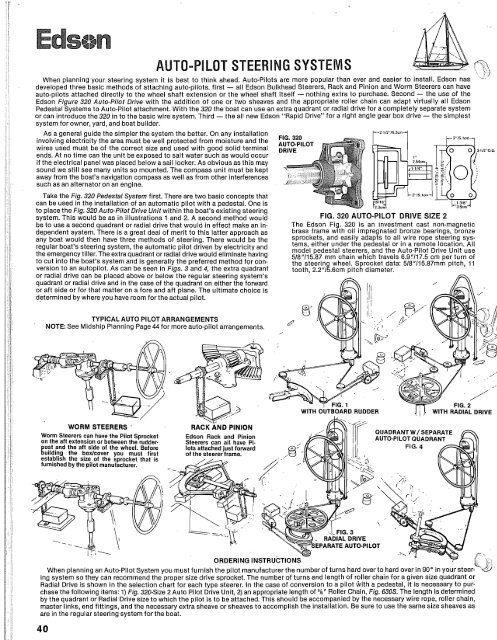
FIG. 320 AUTO-PILOT DRIVE SIZE 2<br />
be to use a second auadrant or radial drive that would in effect make an in- The Edson Fig. 320 is an investment cast non-magnetic<br />
dependent system. here is a great deal of merit to this latter approach as brass frame with oil impregnated bronze bearings, bronze<br />
any boat would then have three methods of steering. There would be the sprockets, and easily adapts to all wire rope steering sys-<br />
:egular boat's steering system, the automatic pilot driven by electricity and<br />
tems, either under the <strong>pedestal</strong> or in a remote location. Ail<br />
model <strong>pedestal</strong> <strong>steerer</strong>s, and the Auto-Pilot Drive Unit use<br />
the emergency tiller. The extra quadrant or radial drive would eliminate having<br />
5/8"115.87 mm chain which travels 6.9"117.5 cm per turn of<br />
to cut into the boat's system and is generally the preferred method for con- the steering wheel. Sprocket data: 5/8"/15.87mm pitch, 11<br />
version to an autopilot. As can be seen in Figs. 3 and 4, the extra quadrant tooth, 2.2"15.6cm pitch diameter.<br />
or radial drive can be placed above or below the regular steering system's<br />
quadrant or radial drive and in the case of the quadrant on either the forward<br />
or aft side or for that matter on a fore and aft plane. The ultimate choice is<br />
determined by where you have room for the actual pilot.<br />
TYPICAL AUTO PILOT ARRANGEMENTS<br />
NOTE: See Midship Planning Page 44 for more auto-pilot arrangements.<br />
WORM STEERERS<br />
Worm Steerers can have the Pilot Sprocket<br />
on the aft extension or between the rudder-<br />
ost and the aft side of the wheel. Before<br />
guilding the boxlcover you must first<br />
establish the size of the sprocket that is<br />
furnished by the pilot manufacturer.<br />
1-6 -<br />
RACK AND PINION<br />
Edson Rack and Pinion<br />
Steerers can all have Pi-<br />
lots attached just fopvard<br />
of the <strong>steerer</strong> frame.<br />
ORDERING INSTRUCTIONS - 7 " L, y-<br />
When planning an Auto-Pilot System you must furnish the pilot manufacturer the number of turns hard over to hard over in 90" in your steer-<br />
ing system so they can recommend the proper size drive sprocket. The number of turns and length of roller chain for a given size quadrant or<br />
Radial Drive is shown in the selection chart for each type <strong>steerer</strong>. In the case of conversion to a pilot hith a <strong>pedestal</strong>, it is necessary to pur-<br />
chase the following items: 1) Fig. 320-Size 2 Auto Pilot Drive Unit, 2) an appropriate length of 5 /~" Roller Chain, Fig. 630s. The length is determined<br />
by the quadrant or Radial Drive size to which the pilot is to be attached. This should be accompanied by the necessary wire rope, roller chain,<br />
master links, end fittings, and the necessary extra sheave or sheaves to accomplish the installation. Be sure to use the same size sheaves as<br />
are in the regular steering system for the boat.<br />
-<br />
[->)<br />
RAPID DRIVE<br />
A MEW CONCEPT IN AUTO-PILOT STEERING<br />
Rapid stands for Rack and Pinion Independent Drive and incorporates the<br />
latest in engineering from Edson. Rapid is adaptable to virtually all types of<br />
boats be they power or sail with wheel or tiller. The steering system must<br />
be of the easily reversing type or in the case of a Hydraulic Steerer be<br />
capable of being totally bypassed. The unit attaches directly to the rudder-<br />
post of the boat and the frame of the Rapid bolts to a flat platform 90" to<br />
the rudderpost. The auto-pilot attaches to the Rapid unit with conventional<br />
sprocket and chain reduction and with Rapid Drive there is no need for<br />
additional rudder stops except in the case of tiller steered conversions.<br />
Precision cast bronze aears orovide effortless ooeration. without notice-<br />
able friction or noise. hi unit'operates withl.8tu;nsof the shaft in 80°0f<br />
rudder travel; your Auto-Pilot manufacturer will specify the sprocket sizes<br />
when you order the pilot.<br />
One of the Edson Rapid Drive features is its compactness. As noted on<br />
the dimensional drawing, the unit takes up only a total width of 191h inches,<br />
and a fore and aft dimension of 11" plus the 3" shaft extension. When<br />
ordering your Auto-Pilot, please note that the shaft for the sprocket is 1"<br />
with a lh" keyway. Maximum Input Rating of the "Rapid" Drive is 1,000<br />
inch pounds based on a%" #41 ten tooth power unit sprocket.<br />
One of the variations of the unit is the Fig. 319 Rapid Drive which in-<br />
corporates the universal and an extra self-aligning bearing. This unit allows<br />
either the basic Rapid Drive to be mounted other than fore or aft and to angle<br />
the shaft extension to facilitate locating the actual Auto-Pilot. The illustra-<br />
tions below show some of the many variations available when using<br />
Rapid Drive.<br />
ORDERING INSTRUCTIONS<br />
Rapid is available in 6 sizes for rudderposts of various sizes. When order-<br />
ing it is necessary to specify the rudderpost bore, keyway size and its<br />
position, that is on the geared segment side or the cap side. The geared<br />
segment can also be attached by pin or set screws. For these methods<br />
pplease see the quadrant page of this catalog. Be sure and specify your pre-<br />
e r r e x h o d .<br />
I I<br />
For Fig. 318 and 319 the following sizes apply:<br />
Size 2 1/2" to 1-3/16 Rudderpost Size<br />
Size 4 1-1/4" to 1-13/16" Rudderpost Size<br />
Size 6 1-7/8" to 2-511 6 Rudderpost Size<br />
Size 8 2-3/8" to 2-13/16 Rudderpost Size<br />
Size 10 2-7/8 to 3-1./2 Rudderpost Size<br />
Size 14 3518" to 5" Rudderpost Size<br />
Weight: 19'hlbs.<br />
The Rapid Drive and the Auto-Pilot must be securely held to a platform. The electrical wirGg to the Auto-Pilot must be of the size recom-<br />
mended by the Auto-Pilot maker and fastened with good solid terminals. The installation must be protected from moisture. As in all exposed<br />
gearing the Rapid must be covered by a clear Lexan or equivalent cover to keep equipment and fingers out of the mechanism. The clear cover<br />
permits ready visual inspection. Maintenance of the Rapid is simple - use #30 or equal Motor oil on the shaft bearings and on the geared<br />
segments and wipe across the bottom of the segment. Water pump grease can also be smeared on at this point. The unit should be inspected<br />
like all steering equipment and it is wise to checkand oil it at least once a week.


