


You also want an ePaper? Increase the reach of your titles
YUMPU automatically turns print PDFs into web optimized ePapers that Google loves.
SlMPLM WORM STEERERS<br />
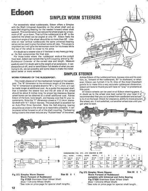
DIMENSIONS FIG. 372 - 373 (INCHES & CM)<br />
1 Size ( A(3731 1 A (3721 1 81373) 1 813721 1 C 1 0 I E I F I G I H I I I<br />
Size 00 0 1 -/<br />
Fig 373 Simplex Worm Steerer-<br />
Fig 372 Simplex Worm Steerer- Size 00 0 1 Worm Forward of'Rudderpost<br />
Worm Forward of Rudderpost complete with Universal and Extra Bearing<br />
Fig 37288 Stainless Steel Wheel Shaft Fig 37355 Stainless Steel Wheel Shaft<br />
(Size 1 Chrome Wheel Shaft) (Size I Chrome Wheel Shaft)<br />
*See note on price page for special shaft lengths. *See note on price page for special shaft length.<br />
12<br />
SIMPLEX WORM STEERERS<br />
For excessively raked rudderposts, Edson offers a Simplex<br />
with the Shaft Universal Assembly on the wheel shaft and an<br />
exfra Self-Aligning Bearing for the needed forward wheel shaft<br />
support. This combination can reduce the wheel angle by a maximum<br />
of 30" up or down. That is if the rudderpost is at 45" to the<br />
waterline the wheel can be angled at only 15". Edson feels the<br />
maximum angleof the wheel should be no more than 20" . Likewise<br />
on near vertical rudderposts the same universallbearing<br />
setup can be used to give the wheel some aft rake. This angle is<br />
important as it will give the helmsman room for his knees while<br />
the top of the wheel is closer to his arms<br />
If in doubt as to <strong>steerer</strong> size or if the boat is very heavy,go larger.<br />
Do Not compromise the final size.<br />
For those boats where the rudderpost ends at the cockpit<br />
floor level, Edson can furnish the Fig 675 Coupling and aFig 782<br />
Rudderpost Extender of the correct size and length. Measure<br />
carefully and if in doubt add to the length of an extension, it can<br />
THREE TYPICAL WORM STEERER INSTALLATIONS<br />
always becut off, andlor send Edson full details of what you are<br />
WORM AFT OF THE RUDDERPOST.<br />
The box that incloses the gear should be watertight yet easitrvina<br />
to do, we can possibly add some ideas to make the instal-<br />
For those boats with room aft of the rudderpost for the ly removable.Thereareseveral sketchesand photographsthat<br />
l$ion better or more versatile.<br />
mechanism of the <strong>steerer</strong>. The most common installation is illustrate Some of the designs that have been SUCC~SS~U~~~ SIMPLEX STEERER<br />
the Fig. 370 which is a straight forward gear with the wheel at employed. Being built up they do offer an excellent seat and<br />
WORM FORWARD OF THE RUDDERPOST:<br />
---<br />
Advise Edson of the rudderpost bore, keyway size and its posi-<br />
the same angle as the rudderpost. The different styles of steer- will also give better visibility over the house. A simple hinged<br />
tion, ie., forward of the rudderpost, 30" to starboard, or what-<br />
ing boxeslseats should be noted in the drawings and folding seat back Can be built, cushions added and the helms-<br />
This model places all of the mechanism forward of the rudderever;<br />
Edson can furnish it to fit. One of the most important<br />
photographs. The more comfortable you make the handling of man will have cruising luxury. In all cases keep the seat low<br />
post. The "B" dimension is the minimum length of the <strong>steerer</strong>s.<br />
points is to make this a very accurate rl;ldderpost dimension.<br />
the boat the more pleasure it gives, and even more important enough so the helmsman's feet are firmly planted on the cock-<br />
Thei'A" dimension isvariabledown to "B"+ 1/2"/1.27cm or it can<br />
Edson will bore to fit and you will have nb or problems at<br />
the longer a helmsman can steer without becoming tired. pit floor or other brace. If they are left dangling the circulation<br />
be made longerat additional cost. As a guide the exposed shaft +,;, ,,;,+<br />
11113 pUIII1.<br />
Note on the drawing above the ~ 370with i~. the optional ~ig. will be cut-off and the position becomes uncomfortable.<br />
'that is between the <strong>steerer</strong> box and the aft side of the wheel<br />
All Edson wheels can be used on all Edson steering gears. If<br />
679 Coupling and the Fig. 782 Rudderpost Extension. These parts MAINTENANCE<br />
should be about 6 inches long for proper leg clearance.Special<br />
in doubt as to the wheel size best suited for your boat it ia)' ?which are necessary when the steering gear is attached to the For maintenance of all Edson Steering Systems we recomwheel<br />
bores can be obtained at a small additional cost. Advise<br />
recommended that you cut a wheel from cardboard and actual- "-top of the original rudderpost, would then place the top of the mend using #30 Oil on all Pivot Points and Water Pump Grease<br />
Edson of the bore, bore length, and keyway size that fit your rely<br />
try it on the boat. Check for clearance, ability to move around ~3) wheel below the 32"/81cm to 33"/84cm recommended height. on the worm itself and on the grease fitting on the centerof the<br />
quirements. Note the "C" dimension covers a 1"/2.54cm diamethe<br />
wheel, etc. If not satisfied, cut anotherwheel size until you * As noted under the above Figure numbers in the catalog these <strong>steerer</strong>. Check the flange alignment by loosening the four bolts<br />
tershaft with '/4"/.635cm keyway. Thisstubshaft is excellent for<br />
get what is best.<br />
parts are available in many sizes and lengths and can be made on the top of the <strong>steerer</strong> and check as on a propellor shaft couan<br />
Auto-Pilot Drive S~rocket. Note the Self-Alianina bearina<br />
to order to fit the boat's special requirements.<br />
pling. The 90" angle is extremely important and this point will<br />
should be as close to the wheel as is reasonably It can<br />
The Worm Steerers are all simple in design and many have cause binding if not correctly aligned.<br />
be placed either forward or aft of the shaft coupling. The bearing<br />
seen hard usage for 15 to 20 years. They are constructed of<br />
being closeto thewheel reducesany "Rubberiness" of the wheel.<br />
time proven materials. The wheel shafts are ~tainless steel<br />
and chrome, the worm shaft steel, the arms and bearings are<br />
cast bronze. The traversing nut is bronze with replaceable<br />
"Babbitt" Threads. The Rudderpost Flanges are cast iron. The<br />
Simplex Steerers have a single - balanced thread with bronze<br />
i_ ,<br />
thrust washers. L, '<br />
I<br />
DIMENSIONS FIG. 370 - 371 (INCHES & CM)<br />
Fig 371 Simplex Worm Steerer- Size 00 0 1<br />
Fig 370 Simplex Worm Steerer- Size00 0 1<br />
Worm Aft of Rudderpost<br />
Fig 370SS Stainless Steel Wheel Shaft<br />
(Size 1 Chrome Wheel Shaft)<br />
*See note on price page for special shaft lengths.<br />
Worm Aft of The Rudderpost<br />
With Universal and Extra Bearing<br />
Fig 371SS Stainless Steel Wheel Shaft<br />
(Size 1 Chrome Wheel Shaft)<br />
*See note on price page for special shaft length.<br />
13


