The ITER toroidal field model coil project
The ITER toroidal field model coil project
The ITER toroidal field model coil project

Create successful ePaper yourself
Turn your PDF publications into a flip-book with our unique Google optimized e-Paper software.
222 A. Ulbricht et al. / Fusion Engineering and Design 73 (2005) 189–327<br />
• Use of SE-Cu in the contact area and in the room<br />
temperature region to reduce the Joule heating.<br />
• Use of clamp contact between the cold end of the<br />
current lead and the bus bar connection.<br />
• Implementation of the so-called “cold gas return”<br />
circuit, which allows to operate the first segment of<br />
the heat exchanger with a higher mass flow rate than<br />
the rest of the heat exchanger.<br />
• Integration of a water cooled flexible jumper cable at<br />
the room temperature end of the current lead to connect<br />
the current lead to the water cooled aluminium<br />
bus bars of the TOSKA facility.<br />
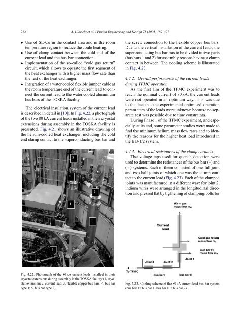
<strong>The</strong> electrical insulation system of the current lead<br />
is described in detail in [10].InFig. 4.22, a photograph<br />
of the two 80 kA current leads installed in their cryostat<br />
extensions during assembly in the TOSKA facility is<br />
presented. Fig. 4.21 shows an illustrative drawing of<br />
the helium-cooled heat exchanger, including the cold<br />
end clamp contact to the superconducting bus bar and<br />
Fig. 4.22. Photograph of the 80 kA current leads installed in their<br />
cryostat extensions during assembly in the TOSKA facility (1, cryostat<br />
extension; 2, current lead; 3, flexible copper bus bars; 4, bus bar<br />
type 1; 5, bus bar type 2).<br />
the screw connection to the flexible copper bus bars.<br />
Due to the vertical installation of the current leads, the<br />
superconducting bus bar has to be divided in two parts<br />
(bus bars 1 and 2) for assembly reasons having a clamp<br />
contact in between. <strong>The</strong> cooling scheme is illustrated<br />
in Fig. 4.23.<br />
4.4.2. Overall performance of the current leads<br />
during TFMC operation<br />
As the first aim of the TFMC experiment was to<br />
reach the nominal current of 80 kA, the current leads<br />
were not operated in an optimum way. This was due<br />
to the fact that the experimental optimised operation<br />
parameters of the leads were unknown because no separate<br />
test was possible due to time constraints.<br />
During Phase 1 of the TFMC experiment, and especially<br />
at its end, some parameter studies were made to<br />
find the minimum helium mass flow rates and to identify<br />
the reasons for the higher heat load introduced in<br />
the BB-1/2 system.<br />
4.4.3. Electrical resistances of the clamp contacts<br />
<strong>The</strong> voltage taps used for quench detection were<br />
used to determine the resistances of the bus bar (+) and<br />
(−) systems. Each of them consisted of one full joint<br />
and two half joints of which one was the clamp contact<br />
to the current lead (Fig. 4.23). Each of the clamped<br />
joints was manufactured in a different way: for joint 2,<br />
indium wires were arranged in the longitudinal direction<br />
and pressed flat by tightening of clamping bolts for<br />
Fig. 4.23. Cooling scheme of the 80 kA current lead bus bar system<br />
(bus bar I = bus bar 1; bus bar II = bus bar 2).