Encounter power system - cadence design systems - Europractice
Encounter power system - cadence design systems - Europractice
Encounter power system - cadence design systems - Europractice

You also want an ePaper? Increase the reach of your titles
YUMPU automatically turns print PDFs into web optimized ePapers that Google loves.
<strong>Encounter</strong> Power System<br />
Unified <strong>power</strong> analysis for faster <strong>design</strong> optimization and signoff<br />
Even timing-clean <strong>design</strong>s can fail on silicon due to lowered operating voltages induced by static<br />
and dynamic IR drop, increased leakage, and temperature variations. Cadence ® <strong>Encounter</strong> ® Power<br />
System enables accurate and high-capacity <strong>power</strong> analysis, helping <strong>design</strong>ers debug and verify<br />
that <strong>power</strong> and IR drop constraints are met across multimillion-gate <strong>design</strong>s and multiple die—<br />
with significant gains in productivity. Integrated with <strong>Encounter</strong> Digital Implementation System<br />
to improve <strong>design</strong> convergence, it is part of a complete Cadence signoff solution that includes<br />
<strong>Encounter</strong> Timing System and <strong>Encounter</strong> Library Characterizer.<br />
<strong>Encounter</strong> Power System<br />
<strong>Encounter</strong> Power System enables<br />
<strong>design</strong> teams to accurately validate<br />
distributed <strong>power</strong> consumption, IR<br />
drop, <strong>power</strong> rail electromigration,<br />
and signal net electromigration<br />
(wire self-heat) for complex <strong>design</strong>s<br />
manufactured on all technology<br />
nodes. When used with <strong>Encounter</strong><br />
Digital Implementation System,<br />
<strong>Encounter</strong> Power System enables<br />
automated <strong>power</strong>-rated optimizations<br />
driven by analysis results,<br />
which improves productivity for<br />
<strong>design</strong> teams.<br />
<strong>Encounter</strong> Power System is built on<br />
production-proven, signoff-quality<br />
algorithms and engines that have<br />
been used to validate thousands of<br />
successful tapeouts. It provides a<br />
comprehensive static and dynamic<br />
<strong>power</strong> integrity analysis and signoff<br />
solution, combining high performance,<br />
capacity, and accuracy with best-inclass<br />
debugging capabilities.<br />
Used throughout the <strong>design</strong> implementation<br />
flow, <strong>Encounter</strong> Power<br />
System enables early floor- and<br />
<strong>power</strong>-planning, together with signoff<br />
analysis and optimizations for block<br />
implementation, chip-level assembly,<br />
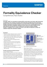
DFM<br />
Signoff Analysis<br />
Performance<br />
Extraction Static Timing<br />
Predictability<br />
Design<br />
Signoff<br />
Accuracy<br />
QoS<br />
Power Integrity<br />
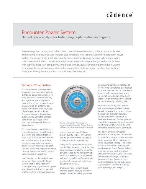
Figure 1: <strong>Encounter</strong> Power System,<br />
combined with <strong>Encounter</strong> Timing System,<br />
offers a complete signoff analysis solution<br />
and pre-tapeout signoff. Using<br />
signoff-quality engines throughout<br />
the <strong>design</strong> flow enables consistent,<br />
convergent results at every step.<br />
Designed for optimal usability, it has<br />
the flexibility to rapidly check that the<br />
<strong>power</strong> rails can supply the amount of<br />
<strong>power</strong> needed during floorplanning,<br />
while also enabling accurate, siliconvalidated<br />
signoff to verify that blocks<br />
and the full chip do not suffer from<br />
<strong>power</strong>-related issues.<br />
DRC / LVS / ERC<br />
<strong>Encounter</strong> Power System drives<br />
multiple optimizations to fix <strong>power</strong><br />
integrity issues, including <strong>power</strong> rail<br />
and via array sizing, size/location of<br />
de-coupling capacitance, size/location<br />
of <strong>power</strong> switches, and I/O placement.<br />
It reports all components of <strong>power</strong><br />
consumption and graphically shows<br />
areas of high dynamic <strong>power</strong> caused<br />
by simultaneously switching logic.<br />
<strong>Encounter</strong> Power System’s <strong>power</strong><br />
calculation engine enables Verilogbased,<br />
early gate-level <strong>power</strong> estimations<br />
as well as signoff-accurate<br />
distributed <strong>power</strong> calculation. It<br />
leverages <strong>Encounter</strong> Timing System’s<br />
signoff timing engine for accurate slew<br />
and timing windows needed during<br />
vectorless dynamic <strong>power</strong> calculation.<br />
For <strong>power</strong>-switch optimization,<br />
<strong>Encounter</strong> Power System can be used<br />
to tune the number of <strong>power</strong> switches<br />
while reporting if high rush current<br />
could cause local IR drop. The combination<br />
of <strong>Encounter</strong> Timing System<br />
and <strong>Encounter</strong> Power System delivers<br />
a comprehensive clock and signal<br />
jitter/skew analysis solution. To enable<br />
accurate chip/package co-<strong>design</strong>,<br />
<strong>Encounter</strong> Power System accepts<br />
package loading models and outputs<br />
a die model of the chip that drives<br />
package <strong>design</strong> and analysis.
Benefits<br />
• Delivers consistent, integrated <strong>power</strong><br />
and IR drop analysis across the<br />
implementation flow, from floorplanning<br />
through optimization and signoff<br />
– Early rail analysis at floor- and <strong>power</strong>planning<br />
stages allows correct-byconstruction<br />
<strong>power</strong> grid <strong>design</strong><br />
– Consistent and accurate <strong>power</strong><br />
analysis engines (integrated or<br />
standalone) improve productivity and<br />
convergence<br />
– Integration with <strong>Encounter</strong> <strong>design</strong><br />
implementation platform allows<br />
access to physical database and<br />
automated engineering change<br />
orders (ECOs)<br />
• Provides a unified signoff analysis<br />
solution<br />
– Integration with <strong>Encounter</strong> Timing<br />
System enables analysis of IR<br />
drop-induced delay variability across<br />
data and clock networks, such as<br />
clock jitter and skew analysis<br />
– Provides consistent engines, interface,<br />
and commands across the flow<br />
• Performs comprehensive, hierarchical<br />
full-chip and package IR drop analysis<br />
– Power grid views of analog, mixedsignal,<br />
custom-digital, or full digital<br />
blocks allow true full-chip IR drop<br />
analysis<br />
– Supports chip/package co-<strong>design</strong><br />
through package and die model<br />
exchange with Cadence Allegro ®<br />
Package Designer<br />
• Boosts productivity and shaves weeks<br />
off tapeout schedules<br />
– Multi-CPU support ensures high<br />
performance<br />
– Pipelined methodology ensures high<br />
capacity and throughput<br />
– Performs incremental and what-if<br />
analysis and exploration<br />
– Supports the Common Power Format<br />
(CPF)<br />
– Provides a GUI-driven and interactive<br />
Tcl command interface<br />
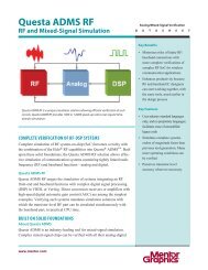
• Allows easy debugging<br />
– Global <strong>power</strong> debug speeds up root<br />
cause analysis<br />
Figure 2: Power and IR drop cross-probing and waveforms<br />
– Integrated waveform and layout<br />
viewers enable fast <strong>power</strong> and IR<br />
debugging<br />
• Offers advanced <strong>power</strong> analysis<br />
capabilities<br />
– Performs analysis across multiple<br />
die for stacked-die, 3D-IC/throughsilicon<br />
via, and <strong>system</strong>-in-package<br />
<strong>design</strong>s<br />
– Performs manufacturing-aware<br />
extraction for advanced node <strong>design</strong>s<br />
– Supports Blech Length for accurate<br />
electromigration analysis<br />
• Supported by major foundries, ASIC<br />
and IP vendors, and integrated device<br />
manufactures<br />
Features<br />
Comprehensive <strong>power</strong> and <strong>power</strong><br />
integrity verification<br />
• Flexible, consistent <strong>power</strong> engine<br />
used for <strong>power</strong> estimation across the<br />
implementation flow<br />
• Gate-level <strong>power</strong> estimation using<br />
Verilog input for early <strong>power</strong> estimation,<br />
with full RTL and gate-level VCD and<br />
SAIF support<br />
<strong>Encounter</strong> Power System<br />
• Accurate post-placement and routing<br />
<strong>power</strong> estimation for <strong>power</strong> grid<br />
optimization and signoff<br />
Easy library generation<br />
• Detailed <strong>power</strong> grid view (PGV)<br />
generation using readily available SPICE<br />
subcircuits<br />
• Detailed PGV generation using<br />
industry-standard LVS rule decks<br />
• On-the-fly device and coupling<br />
capacitance characterization using the<br />
embedded Cadence Virtuoso ® Spectre ®<br />
Simulator<br />
• Pass/fail report capabilities to analyze<br />
contents of PGVs with guidance on<br />
causes of failure<br />
• Layout-aware Power System Viewer<br />
(PSViewer) for graphically viewing and<br />
debugging PGVs<br />
• Automatic spawning of library generation<br />
jobs for macros and memories<br />
www.<strong>cadence</strong>.com 2
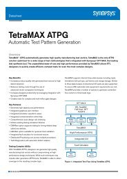
Figure 3: Global <strong>power</strong> debug<br />
Seamless data import and input-data<br />
sanity checking<br />
• Flexible <strong>design</strong> imports using <strong>Encounter</strong><br />
database, OpenAccess, or third-party<br />
<strong>design</strong>s<br />
• Embedded <strong>design</strong> sanity checks such as<br />
completeness of LEF library data, timing<br />
library data, physical and logical netlist<br />
annotation, and SPEF annotation<br />
• Fast structural <strong>power</strong> grid verification to<br />
identify missing vias and disconnected<br />
<strong>power</strong> pins<br />
• Tight integration with the <strong>Encounter</strong><br />
Timing System signoff timing engine,<br />
for seamless transfer of slews and<br />
arrival times<br />
Powerful GUI<br />
• Command console with full Tcl support,<br />
command completion, history, and<br />
context highlighting<br />
• Script editor to evaluate scripts with<br />
ability to crosslink and expand Tcl<br />
procedures<br />
Easy debugging<br />
• Global <strong>power</strong> debug for analyzing<br />
<strong>power</strong> consumption at different levels<br />
of hierarchy, cell type, <strong>power</strong> net,<br />
<strong>power</strong> domain, clock domain, etc., with<br />
pie charts and histograms<br />
• Integrated full-featured waveform<br />
viewer for studying dynamic <strong>power</strong> and<br />
IR drop waveforms, with composite<br />
waveform creation capabilities across<br />
<strong>design</strong> hierarchies and clock domains<br />
• Embedded <strong>Encounter</strong> Layout Viewer<br />
with ability to cross-probe <strong>power</strong> and<br />
IR drop information<br />
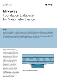
• Instance-based effective resistance<br />
plots with automatic least-resistive path<br />
highlighting<br />
<strong>Encounter</strong> Power System<br />
• HTML reporting for easy navigation of<br />
results<br />
• Fast what-if analysis, enabling quick<br />
experimentation<br />
Early rail analysis<br />
Floorplanning and <strong>power</strong> planning<br />
<strong>design</strong>ers can use <strong>Encounter</strong> Power<br />
System engines to rapidly prototype their<br />
I/O placement, macro placement, and<br />
<strong>power</strong> grid structure early in the <strong>design</strong>.<br />
Consistency of the engines between early<br />
rail analysis and <strong>Encounter</strong> Power System<br />
removes correlation risks, improves<br />
productivity, and speeds <strong>design</strong> closure.<br />
Vector profiling<br />
<strong>Encounter</strong> Power System includes multiple<br />
vector profiling options to help you study<br />
VCD profiles textually and graphically.<br />
Activity-based vector profiling enables<br />
fast identification of high-activity regions<br />
of VCDs. A fast vector <strong>power</strong>-profiling<br />
option calculates switching <strong>power</strong> of the<br />
<strong>design</strong> over time. The accurate vector<br />
<strong>power</strong>-profiling option allows full <strong>power</strong><br />
estimation of a VCD, with activity propagation<br />
capabilities for non-annotated<br />
nodes.<br />
Automatic de-coupling capacitance<br />
optimization<br />
<strong>Encounter</strong> Power System can calculate<br />
and recommend the amount of additional<br />
de-coupling capacitance necessary to<br />
limit the dynamic IR drop to user-specified<br />
limits. This recommended additional<br />
de-coupling capacitance can then drive an<br />
automated optimization flow throughout<br />
the <strong>Encounter</strong> platform, where filler<br />
cells are swapped with de-coupling<br />
capacitance cells. For low-<strong>power</strong> <strong>design</strong>s,<br />
Figure 4: Effective resistance plots with automatic least-resistive path highlighting<br />
www.<strong>cadence</strong>.com 3
Figure 5: HTML reports<br />
this flow can be used to remove extra<br />
de-coupling capacitance cells in the<br />
<strong>design</strong>, improving leakage and yield.<br />
Chip-package co-<strong>design</strong><br />
<strong>Encounter</strong> Power System integration with<br />
Allegro Package Designer enables easy<br />
hand-off of package and die models.<br />
<strong>Encounter</strong> Power System enables chip<br />
<strong>design</strong>ers to create an abstract parasitics<br />
and dynamic current profile of the die for<br />
package <strong>design</strong>ers. It also takes in two or<br />
n-port package models to enable accurate<br />
IR drop analysis, taking into account the<br />
package effects.<br />
Analysis of IR drop impact on timing<br />
and signal integrity<br />
<strong>Encounter</strong> Power System calculates<br />
instance operating voltages based on<br />
the switching windows associated with<br />
each instance. It then provides this information<br />
to <strong>Encounter</strong> Timing System,<br />
which calculates the impact of IR drop<br />
on delay and signal integrity-generated<br />
noise. <strong>Encounter</strong> Power System can also<br />
generate dynamic IR drop and groundbounce<br />
waveforms for critical paths,<br />
allowing <strong>Encounter</strong> Timing System to<br />
accurately trace and analyze such paths.<br />
Clock and signal jitter and skew<br />
analysis<br />
The delay variation caused by dynamic<br />
operating voltages on the clock networks<br />
and signal paths can cause additional<br />
set-up and hold violations in a <strong>design</strong>.<br />
By calculating the effective operating<br />
voltage of the clock network and signal<br />
path elements, <strong>Encounter</strong> Power System<br />
enables <strong>Encounter</strong> Timing System to more<br />
accurately analyze clock jitter, clock skew,<br />
and signal delay variability during static<br />
timing analysis (STA). This analysis allows<br />
<strong>Encounter</strong> Timing System to identify<br />
problematic clock network elements and<br />
to create and run a complete jitter-sensitized<br />
SPICE trace.<br />
Power-up analysis and <strong>power</strong>-switch<br />
optimization<br />
Many low-<strong>power</strong> <strong>design</strong>s now include<br />
switched blocks through the use of <strong>power</strong><br />
switches. These blocks are only turned<br />
on when needed, saving leakage <strong>power</strong><br />
when not in use. <strong>Encounter</strong> Power System<br />
analyzes the <strong>power</strong>-on and <strong>power</strong>-off<br />
scenarios of these blocks, creating<br />
engineering change orders (ECOs) to<br />
optimize <strong>power</strong>-switch size and location.<br />
This ensures that the block’s rush-current<br />
during <strong>power</strong>-up will not impact the<br />
neighboring logic, and that the static and<br />
dynamic IR drop within the block is within<br />
expected budgets.<br />
<strong>Encounter</strong> Power System<br />
Hierarchical IR drop analysis<br />
<strong>Encounter</strong> Power System uses <strong>power</strong><br />
grid views (PGVs) as the building blocks<br />
for hierarchical <strong>power</strong> grid analysis.<br />
These <strong>power</strong> models can be created by<br />
automated library characterization within<br />
<strong>Encounter</strong> Power System, or following<br />
block-level analysis by Virtuoso Power<br />
System. After IR drop analysis, both<br />
products create PGVs for use in <strong>Encounter</strong><br />
Power System during full-chip static and<br />
dynamic runs. This allows study of IR drop<br />
across a complex <strong>system</strong> on chip that<br />
includes digital (ASIC), custom digital,<br />
analog, and mixed-signal components<br />
and <strong>power</strong> domains.<br />
Standard Interface Support<br />
• Mandatory <strong>design</strong> data<br />
– Timing libraries<br />
– Verilog<br />
– SDC<br />
– LEF<br />
– DEF<br />
– SPEF<br />
– SPICE subcircuits and GDS for <strong>design</strong><br />
components<br />
– Power pad location<br />
– Extraction tech file for QRC or<br />
process file<br />
• Optional <strong>design</strong> data<br />
– Common Power Format (CPF) file<br />
– Package model<br />
– VCD<br />
Platforms<br />
• Sun Solaris 8 or 9 (32-bit, 64-bit)<br />
• HP-UX 11.0 (32-bit, 64-bit)<br />
• Opteron Linux RHEL 3.0 (64-bit)<br />
• Red Hat Linux RHEL 2.1 (32-bit)<br />
• IBM AIX 5.1 (32-bit, 64-bit)<br />
www.<strong>cadence</strong>.com 4
Cadence Services and Support<br />
• Cadence application engineers can<br />
answer your technical questions by<br />
telephone, email, or Internet—they can<br />
also provide technical assistance and<br />
custom training<br />
• Cadence certified instructors teach<br />
more than 70 courses and bring<br />
their real-world experience into the<br />
classroom<br />
• More than 25 Internet Learning<br />
Series (iLS) online courses allow you<br />
the flexibility of training at your own<br />
computer via the Internet<br />
• Cadence Online Support gives you 24x7<br />
online access to a knowledgebase of<br />
the latest solutions, technical documentation,<br />
software downloads, and more<br />
DEF Verilog<br />
Power<br />
Plots<br />
SPEF<br />
Power<br />
Reports<br />
Power<br />
Waveforms<br />
= Required Input<br />
= Input for Library Generation<br />
Figure 6: <strong>Encounter</strong> Power System inputs and outputs<br />
Timing<br />
Libraries<br />
GDS<br />
IRdrop/EM<br />
Reports<br />
IRdrop<br />
Waveforms<br />
<strong>Encounter</strong> Power System<br />
Cadence is transforming the global electronics industry through a vision called EDA360.<br />
With an application-driven approach to <strong>design</strong>, our software, hardware, IP, and services help<br />
customers realize silicon, SoCs, and complete <strong>system</strong>s efficiently and profitably. www.<strong>cadence</strong>.com<br />
© 2012 Cadence Design Systems, Inc. All rights reserved. Cadence, the Cadence logo, Allegro, <strong>Encounter</strong>, Spectre, and Virtuoso are registered<br />
trademarks of Cadence Design Systems, Inc. All others are properties of their respective holders. 22540 01/12 MK/DM/PDF<br />
LEF<br />
Spice<br />
Subckts<br />
SDC<br />
Power<br />
Pads<br />
VCD<br />
<strong>Encounter</strong><br />
Power<br />
System<br />
Package<br />
IRdrop/EM<br />
Plots<br />
= Optional Input<br />
= Output