

ARM Processor Instruction Set
ARM Processor Instruction Set
ARM Processor Instruction Set

You also want an ePaper? Increase the reach of your titles
YUMPU automatically turns print PDFs into web optimized ePapers that Google loves.
5.4.2 Shifts<br />
<strong>ARM</strong>7500FE Data Sheet<br />
<strong>ARM</strong> DDI 0077B<br />
<strong>ARM</strong> <strong>Processor</strong> <strong>Instruction</strong> <strong>Set</strong><br />
If the S bit is set (and Rd is not R15):<br />
• the V flag in the CPSR will be set if an overflow occurs into bit 31 of the result;<br />
this may be ignored if the operands were considered unsigned, but warns of<br />
a possible error if the operands were 2's complement signed<br />
• the C flag will be set to the carry out of bit 31 of the ALU<br />
• the Z flag will be set if and only if the result was zero<br />
• the N flag will be set to the value of bit 31 of the result (indicating a negative<br />
result if the operands are considered to be 2's complement signed).<br />
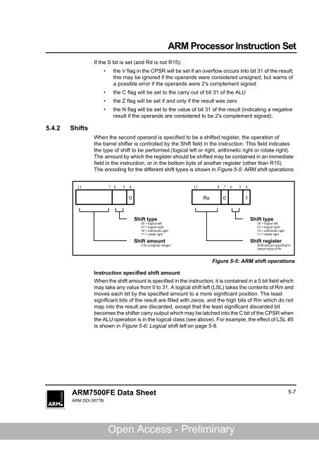
When the second operand is specified to be a shifted register, the operation of<br />
the barrel shifter is controlled by the Shift field in the instruction. This field indicates<br />
the type of shift to be performed (logical left or right, arithmetic right or rotate right).<br />
The amount by which the register should be shifted may be contained in an immediate<br />
field in the instruction, or in the bottom byte of another register (other than R15).<br />
The encoding for the different shift types is shown in Figure 5-5: <strong>ARM</strong> shift operations.<br />
11 7 6 5 4<br />
0 Rs 0 1<br />
Shift type<br />
00 = logical left<br />
01 = logical right<br />
10 = arithmetic right<br />
11 = rotate right<br />
Shift amount<br />
5 bit unsigned integer<br />
11 8 7 6 5 4<br />
Open Access - Preliminary<br />
Shift type<br />
00 = logical left<br />
01 = logical right<br />
10 = arithmetic right<br />
11 = rotate right<br />
Shift register<br />
Shift amount specified in<br />
bottom byte of Rs<br />
Figure 5-5: <strong>ARM</strong> shift operations<br />
<strong>Instruction</strong> specified shift amount<br />
When the shift amount is specified in the instruction, it is contained in a 5 bit field which<br />
may take any value from 0 to 31. A logical shift left (LSL) takes the contents of Rm and<br />
moves each bit by the specified amount to a more significant position. The least<br />
significant bits of the result are filled with zeros, and the high bits of Rm which do not<br />
map into the result are discarded, except that the least significant discarded bit<br />
becomes the shifter carry output which may be latched into the C bit of the CPSR when<br />
the ALU operation is in the logical class (see above). For example, the effect of LSL #5<br />
is shown in Figure 5-6: Logical shift left on page 5-8.<br />
5-7