

ARM Processor Instruction Set
ARM Processor Instruction Set
ARM Processor Instruction Set

Create successful ePaper yourself
Turn your PDF publications into a flip-book with our unique Google optimized e-Paper software.
<strong>ARM</strong> <strong>Processor</strong> <strong>Instruction</strong> <strong>Set</strong><br />
5-8<br />
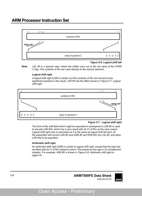
31 27 26 0<br />
carry out<br />
contents of Rm<br />
value of operand 2<br />
Figure 5-6: Logical shift left<br />
Note: LSL #0 is a special case, where the shifter carry out is the old value of the CPSR<br />
C flag. The contents of Rm are used directly as the second operand.<br />
Logical shift right<br />
A logical shift right (LSR) is similar, but the contents of Rm are moved to less<br />
significant positions in the result. LSR #5 has the effect shown in Figure 5-7: Logical<br />
shift right.<br />
contents of Rm<br />
value of operand 2<br />
Figure 5-7: Logical shift right<br />
The form of the shift field which might be expected to correspond to LSR #0 is used<br />
to encode LSR #32, which has a zero result with bit 31 of Rm as the carry output.<br />
Logical shift right zero is redundant as it is the same as logical shift left zero, so<br />
the assembler will convert LSR #0 (and ASR #0 and ROR #0) into LSL #0, and allow<br />
LSR #32 to be specified.<br />
Arithmetic shift right<br />
An arithmetic shift right (ASR) is similar to logical shift right, except that the high bits<br />
are filled with bit 31 of Rm instead of zeros. This preserves the sign in 2's complement<br />
notation. For example, ASR #5 is shown in Figure 5-8: Arithmetic shift right on<br />
page 5-9.<br />
<strong>ARM</strong>7500FE Data Sheet<br />
<strong>ARM</strong> DDI 0077B<br />
0 0 0 0 0<br />
31 5 4<br />
0<br />
0 0 0 0 0<br />
carry out<br />
Named Partner Open Confidential Access - Preliminary - Preliminary Draft