Ultrasonic flow sensor - Hachflow
Ultrasonic flow sensor - Hachflow
Ultrasonic flow sensor - Hachflow

You also want an ePaper? Increase the reach of your titles
YUMPU automatically turns print PDFs into web optimized ePapers that Google loves.
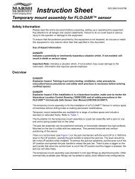
Note: To connect other instruments, contact the manufacturer for wiring details.Select a relay to use for <strong>flow</strong> pacing.1. Open the controller cover.2. Connect the bare lead auxiliary cable (white wire) for the poweroutput from the sampler to the NO (normally open) terminal.3. Connect to the COM (normally common) terminal.• SD900 sampler controller: Connect the pin C (orange wire) forthe pulse current input to the COM (normally common) terminal.• 900MAX sampler controller: Connect the pin C (yellow wire) forthe pulse current input to the COM (normally common) terminal.4. Close the controller cover and tighten the cover screws.5. Apply power to the controller.Make sure to specify the <strong>flow</strong> pulse volume and pulse width in the<strong>sensor</strong> setup (Configure the <strong>sensor</strong> for <strong>flow</strong> pacing on page 15). Makesure to configure the relay setup (Configure relays for <strong>flow</strong> pacingon page 15). Make sure to configure the sampler for the <strong>flow</strong> pacingmode (refer to the sampler documentation).Configure the <strong>sensor</strong> for <strong>flow</strong> pacingMake sure to specify the <strong>flow</strong> pulse volume and pulse width in the<strong>sensor</strong> setup.1. Push the MENU key and select SENSOR SETUP and push ENTER.2. Select CONFIGURE>SET VOL/PULSE and then PULSE WIDTH toset values.OptionDescriptionConfigure relays for <strong>flow</strong> pacingUse the instructions to configure the <strong>flow</strong> pacing. Refer to the controllermanual for more information about relay setup.1. From the sc200 SETUP menu, select RELAY SETUP.2. Select a relay from the list.3. Select ACTIVATION. Select the options for activation.OptionLOW ALARMHIGH ALARMLOWDEADBANDHIGHDEADBANDDescriptionSets the value where the relay will turn on in response todecreasing measured value. Set the value to 0.Sets the value where the relay will turn on in response toincreasing measured value. Set the value equal to the<strong>flow</strong> pulse volume (the value set for SET VOL/PULSE).Sets the range where the relay remains on after themeasured value increases above the low alarm value. Setthe value to 0.Sets the range where the relay remains on after themeasured value decreases below the high alarm value.For example, if the high alarm is set for 1000 gallons andthe high deadband is set for 10, the relay remains onbetween 990 and 1000. Default is 5% of the range.4. From the Relay Setup menu, select SELECT SOURCE>US(ultrasonic <strong>sensor</strong>) and push ENTER.5. Select SET PARAMETER>PULSED VOLUME.6. Select SET FUNCTION>ALARM.7. Use the SETTINGS>TEST/MAINT menu to make sure the relayoperates correctly.SET VOL/PULSESets the volume output to send the pulse to the externaldevice. The measure unit for the pulsed volume outputmatches the measure unit for the general volume fromthe <strong>sensor</strong> configuration (e.g. 1000 US GALLONS)MaintenanceW A R N I N GPULSE WIDTHSets the length of time for the closed relay. Set the valueto 1 second (minimum value). Factory default = 0.Multiple hazards. Only qualified personnel must conduct the tasksdescribed in this section of the document.English 15