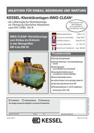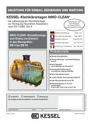
KESSEL-Kleinkläranlagen InnoClean PLUS
KESSEL-Kleinkläranlagen InnoClean PLUS
KESSEL-Kleinkläranlagen InnoClean PLUS

You also want an ePaper? Increase the reach of your titles
YUMPU automatically turns print PDFs into web optimized ePapers that Google loves.
During the intermediate storage of the small sewage treatment<br />
plant and until completion of the installation<br />
work, suitable safeguarding measures must be taken at<br />
the building site to prevent accidents and damage to the<br />
small sewage treatment plant.<br />
The chapter "Safety instructions" must be heeded.<br />
Installation requirements<br />
Installation must only be carried out by companies who are<br />
in possession of the technical experience, suitable implements<br />
and equipment as well as adequately trained personnel.<br />
A measurement of the soil conditions with a view to its<br />
structural suitability must have been carried out (soil classification<br />
for structural purposes DIN 18196). The maximum<br />
occurring ground water level must also be determined before<br />
the start of construction work. A sufficient drainage of seepage<br />
water is compulsory for soils that are impermeable to<br />
water. The types of loads occurring such as maximum travelling<br />
loads and installation depth must have been clarified.<br />
Brief overview installation steps (see also 4.1 to 4.12)<br />
1. Deciding on the place of installation.<br />
2. Excavating the excavation pit.<br />
3. Preparing the blinding layer (tank bed) .<br />
4. Placing the tank into the excavation pit..<br />
5. Filling all chambers of the tank halfway up with water to<br />
guarantee stability.<br />
6. Backfilling the excavation pit with gravel in layers (to<br />
below the outlet) and compacting.<br />
7. Pipe installation for the inlets and drains as well as the<br />
ventilation line and cable conduit lines.<br />
8. Laying the ventilation hose and control line inside the<br />
cable conduit.<br />
9. Attaching the attachment piece and fastening with clamping<br />
ring.<br />
10. Concluding filling of the tank.<br />
11. Installing and connecting wall bracket, compressor and<br />
control.<br />
12. Commissioning the plant (see chapter 5).<br />
4.1 Place of installation<br />
Immediately before placing the tank into the excavation pit,<br />
the technical expert of the company that has been commissioned<br />
to carry out the installation has to check and certify<br />
the following:<br />
- The sound condition of the tank wall;<br />
- The proper condition of the excavation pit with a view to its<br />
dimensions and base bedding;<br />
- Consistence of the filling material graining.<br />
The clearance between control unit and tank may amount to<br />
a maximum of 12.6 m (option: 30 m - hose package = clearance<br />
27.5 m). If this proves to be insufficient, the control unit<br />
and the compressor can be installed inside an optional control<br />
cabinet.<br />
4. Installation and assembly<br />
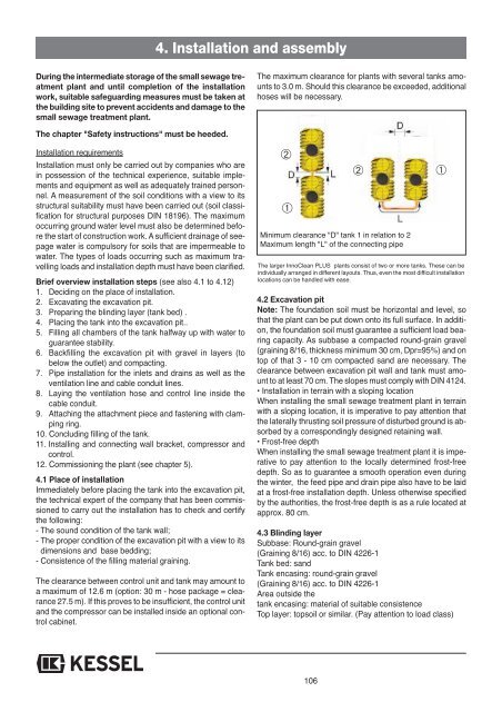
The maximum clearance for plants with several tanks amounts<br />
to 3.0 m. Should this clearance be exceeded, additional<br />
hoses will be necessary.<br />
➁<br />
➀<br />
The larger <strong>InnoClean</strong> <strong>PLUS</strong> plants consist of two or more tanks. These can be<br />
individually arranged in different layouts. Thus, even the most difficult installation<br />
locations can be handled with ease.<br />
4.2 Excavation pit<br />
Note: The foundation soil must be horizontal and level, so<br />
that the plant can be put down onto its full surface. In addition,<br />
the foundation soil must guarantee a sufficient load bearing<br />
capacity. As subbase a compacted round-grain gravel<br />
(graining 8/16, thickness minimum 30 cm, Dpr=95%) and on<br />
top of that 3 - 10 cm compacted sand are necessary. The<br />
clearance between excavation pit wall and tank must amount<br />
to at least 70 cm. The slopes must comply with DIN 4124.<br />
• Installation in terrain with a sloping location<br />
When installing the small sewage treatment plant in terrain<br />
with a sloping location, it is imperative to pay attention that<br />
the laterally thrusting soil pressure of disturbed ground is absorbed<br />
by a correspondingly designed retaining wall.<br />
• Frost-free depth<br />
When installing the small sewage treatment plant it is imperative<br />
to pay attention to the locally determined frost-free<br />
depth. So as to guarantee a smooth operation even during<br />
the winter, the feed pipe and drain pipe also have to be laid<br />
at a frost-free installation depth. Unless otherwise specified<br />
by the authorities, the frost-free depth is as a rule located at<br />
approx. 80 cm.<br />
4.3 Blinding layer<br />
Subbase: Round-grain gravel<br />
(Graining 8/16) acc. to DIN 4226-1<br />
Tank bed: sand<br />
Tank encasing: round-grain gravel<br />
(Graining 8/16) acc. to DIN 4226-1<br />
Area outside the<br />
tank encasing: material of suitable consistence<br />
Top layer: topsoil or similar. (Pay attention to load class)<br />
106<br />
➁<br />
Minimum clearance "D" tank 1 in relation to 2<br />
Maximum length "L" of the connecting pipe<br />
➀