
Create successful ePaper yourself
Turn your PDF publications into a flip-book with our unique Google optimized e-Paper software.
ITALIANO<br />
ENGLISH DEUTSCH FRANÇAIS<br />
ESPAÑOL<br />
- L'azionamento dei due cilindri idraulici<br />
«A» per la regolazione dei rulli posteriori<br />
che determinano la profondità di<br />
lavoro (accessorio a richiesta).<br />
Riconoscimento funzione dei<br />
tubi<br />
Tutti i tubi idraulici della macchina hanno<br />
delle etichette adesive di riconoscimento<br />
che sono rappresentate da (Fig.17):<br />
1: Abbassamento rulli posteriori.<br />
2: Sollevamento rulli posteriori.<br />
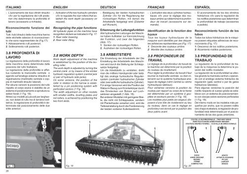
3.8 PROFONDITÀ DI<br />
LAVORO<br />
La regolazione della profondità di lavoro<br />
della macchina viene determinata dalla<br />
posizione del rullo livellatore.<br />
La regolazione della profondità si effettua<br />
ruotando la manovella centrale o<br />
agendo sull'analogo sistema idraulico di<br />
registrazione (martinetto centrale o coppia<br />
di martinetti idraulici laterali).<br />
Per alcune versioni la posizione del rullo<br />
rispetto al corpo erpice è stabilita da un<br />
sistema di posizionamento a spinatura su<br />
settori forati (1 Fig. 18).<br />
Altresì sui modelli più piccoli per larghezza,<br />
non dotati di rullo ma di lamiera livellatrice,<br />
la regolazione di profondità è determinata<br />
dal posizionamento delle due<br />
slitte anteriori.<br />
- Activation of the two hydraulic cylinders<br />
«A» to regulate the rear rollers that establish<br />
the work depth (accessory on<br />
request).<br />
Recognizing the pipe functions<br />
All hydraulic pipes on the machine have<br />
recognition stickers as indicated in Fig. 17:<br />
1: Rear roller lowering.<br />
2: Rear roller lifting.<br />
3.8 WORK DEPTH<br />
Work depth adjustment of the machine<br />
is established by the position of the levelling<br />
roller.<br />
The work depth is adjusted by turning the<br />
central crank or by means of the similar<br />
hydraulic regulation system (central jack<br />
or pair of hydraulic side jacks).<br />
On some versions, the position of the<br />
roller in relation to the harrow is established<br />
by a pin positioning system with<br />
perforated sectors (1 Fig. 18).<br />
The width adjustment on other models<br />
with smaller widths, levelling plates and<br />
not rollers, is achieved by positioning the<br />
two front skids.<br />
- Betätigung der beiden hydraulischen<br />
Zylinder «A» für die Regulierung der<br />
rückseitigen Rollen, mit denen die<br />
Arbeitstiefe festgelegt wird (Zübehör<br />
auf Wunsch).<br />
Erkennung der Leitungsfunktion<br />
Alle hydraulischen Leitungen der Maschine<br />
haben Aufkleber zur Kennzeichnung<br />
der Funktion, und zwar die folgenden<br />
(Abb. 17):<br />
1: Senken der rückseitigen Rollen.<br />
2: Ausheben der rückseitigen Rollen.<br />
3.8 ARBEITSTIEFE<br />
Die Einstellung der Arbeitstiefe der Die<br />
Einstellung der Arbeitstiefe des Maschinen<br />
wird durch die Stellung der Schleppwalze<br />
festgelegt.<br />
Um die Arbeitstiefe zu verstellen, dreht<br />
man die mittlere Handspindel oder betätigt<br />
das analoge hydraulische Reguliersystem<br />
(zentraler hydraulischer Zylinder<br />
oder zwei seitliche hydraulische Zylinder).<br />
Für einige Versionen wird die Position der<br />
Walze im Bezug zum Krümlerkörper durch<br />
das Einstecken von Bolzen auf Lochsektoren<br />
eingestellt (1 Abb. 18).<br />
Bei anderen Modellen mit geringerer Breite,<br />
die nicht mit Schleppwalze, sondern<br />
mit Planierhaube versehen sind, wird die<br />
Tiefeneinstellung durch die Positionierung<br />
der beiden vorderen Kufenbestimmt.<br />
- L’activation des deux cylindres hydrauliques<br />
«A» pour le réglage des rouleaux<br />
arrière qui déterminent la profondeur<br />
de travail (accessoire sur demande).<br />
Identification de la fonction des<br />
tuyaux<br />
Tous les tuyaux hydrauliques de la<br />
maquine sont identifiés par des étiquettes<br />
adhésives représentées par (Fig. 17):<br />
1: Descente des rouleaux arrière.<br />
2: Montée des rouleaux arrière.<br />
3.8 PROFONDEUR DE<br />
TRAVAIL<br />
Le réglage de la profondeur de travail de<br />
la machine est déterminé par la position<br />
du rouleau de nivellement.<br />
Pour régler la profondeur de travail il faut<br />
tourner la manivelle centrale ou bien intervenir<br />
sur le système hydraulique analogue<br />
de réglage (vérin central ou vérins<br />
hydrauliques latéraux).<br />
Pour certaines versions la position du<br />
rouleau par rapport au corps de la herse<br />
est déterminée par un système à goupilles<br />
et secteurs percés (1 Fig. 18).<br />
Les modèles plus petits (en largeur) disposent<br />
d’une tôle de nivellement au lieu<br />
du rouleau; dans ce cas le réglage en<br />
profondeur est donné par la position des<br />
deux patins avant.<br />
- El accionamiento de los dos cilindros<br />
hidráulicos «A» para la regulación de<br />
los rodillos posteriores que determinan<br />
la profundidad de trabajo (accesorios<br />
a pedido).<br />
Reconocimiento función de los<br />
tubos<br />
Todos los tubos hidráulicos de la máquina<br />
poseen etiquetas adhesivas de reconocimiento<br />
(Fig. 17):<br />
1: Descenso de los rodillos posteriores.<br />
2: Alzamiento rodillos posteriores.<br />
3.8 PROFUNDIDAD DE<br />
TRABAJO<br />
La regulación de la profundidad de trabajo<br />
de la máquinas la determina la posición<br />
del rodillo nivelador.<br />
La regulación de la profundidad se efectúa<br />
girando la manivela central u operando<br />
con el análogo sistema hidráulico de<br />
regulación (gato central o par de gatos<br />
hidráulicos laterales).<br />
Para algunas versiones la posición del<br />
rodillo respecto al cuerpo grada se establece<br />
con un sistema de posicionamiento<br />
con clavijas sobre sectores perforados<br />
(1 Fig. 18).<br />
Del mismo modo en los modelos más pequeños<br />
por ancho, que no poseen rodillo<br />
sino chapa niveladora, la regulación de profundidad<br />
está determinada por el posicionamiento<br />
de las dos guías anteriores.<br />
1<br />
1<br />
1<br />
COLTELLO BI-DIREZIONALE - TWO-WAY KNIVE<br />
ZWEI RICHTUNGEN ARBEITENDE MESSER<br />
COUTEAU BIDIRECTIONNEL - CUCHILLA BI-DIRECCIONALE<br />
1 2<br />
Fig. 18 Fig. 19<br />
28<br />
Fig. 20<br />
SODO<br />
HARD GROUND<br />
BODEN<br />
FERME<br />
COMPACTOS<br />
ARATO<br />
AFTER PLOUGHING<br />
PFLUG<br />
LABOUR<br />
ARADO