Betriebsanleitung Operating Manual Mode d ... - Bennett Scientific
Betriebsanleitung Operating Manual Mode d ... - Bennett Scientific
Betriebsanleitung Operating Manual Mode d ... - Bennett Scientific

You also want an ePaper? Increase the reach of your titles
YUMPU automatically turns print PDFs into web optimized ePapers that Google loves.
k<br />
1<br />
2<br />
3<br />
b<br />
c<br />
a<br />
3<br />
b 2<br />
b 6<br />
b+c<br />
b+c<br />
6 2<br />
f<br />
4<br />
4<br />
3<br />
5<br />
1<br />
k<br />
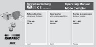
1 Montageplatte montieren<br />
– 2 Schrauben (b) und Fächerscheiben<br />
(c) vom Pumpenkopf<br />
entfernen.<br />
– Montageplatte (3) mit den 2<br />
Schrauben (b) und Fächerscheiben<br />
(c) am Pumpenkopf<br />
(a) befestigen.<br />
Die 4 Versenkungen müssen<br />
gegen den Pumpenkopf<br />
gerichtet sein.<br />
2 Kupplung montieren<br />
– Setzen Sie das Kupplungsstück<br />
(2) auf die Kolbenwelle<br />
Die Kupplungsschraube (6)<br />
muss gegen den flachen Teil<br />
der Kolbenwelle gerichtet sein.<br />
– Stoßen Sie das Kupplungsstück<br />
(2) Richtung Montageplatte<br />
(3) bis die Innenfläche<br />
der Kupplung mit der Stirnseite<br />
der Kopfwelle bündig ist.<br />
Ziehen Sie die Schraube (6)<br />
der Kupplung mit dem Innen-<br />
Sechskantschlüssel 2.5 mm (5)<br />
fest.<br />
3 Pumpenkopf montieren<br />
– Skala des roten Skalenrings<br />
(f) nach oben drehen<br />
– Montageplatte so halten,<br />
dass Schrauben (b) oben und<br />
unten sind. Kupplung so<br />
drehen, dass die Kupplungshälften<br />
des Pumpenkopfes und<br />
des Antriebs ineinander greifen.<br />
Die Kopf-Einheit bis zum<br />
Anschlag einführen.<br />
– Die 4 Senkschrauben (4)<br />
festziehen.<br />
1 Attaching the mounting plate<br />
– Remove screws (b) and serrated<br />
lock washers (c) from the<br />
pump head.<br />
– Fasten the mounting-plate<br />
(3) on the pump head with the<br />
2 screws (b) and serrated lock<br />
washers (c).<br />
The 4 countersinks must<br />
be concave to the pump head.<br />
2 Fixing the coupling<br />
– Put the coupling (2) on the<br />
piston shaft. The hexagon<br />
socket screw (6) must face the<br />
flat part of the motor shaft.<br />
– Push the coupling piece (2)<br />
towards the back of the mounting<br />
plate (3) until the inner<br />
face of the coupling meets the<br />
front of the head shaft. Tighten<br />
the coupling screw (6) with<br />
the Allan key 2.5 mm (5).<br />
3 Mounting the pump head<br />
– The scale of the red flow<br />
control ring (f) must be pointing<br />
upwards<br />
– Hold the mounting plate<br />
in such a way, that the screws<br />
(b) are on the top and at the<br />
bottom. Turn the coupling, so<br />
that the two coupling halves of<br />
pump head and drive engage.<br />
Insert the pump head assembly<br />
and push it on as far as it will<br />
go.<br />
– Drive in the countersunk<br />
head-screws (4).<br />
1 Installation<br />
de la palque de montage<br />
– Dévisser les vis (b) et les enlever<br />
de la tête de pompe FMI<br />
avec les rondelles (c).<br />
– Fixer la plaque de montage<br />
(3) sur la tête de pompe avec<br />
les 2 vis (b) et les rondelles (c).<br />
Les 4 noyures doivent être<br />
dirigées contre la tête de pompe<br />
FMI.<br />
2 Installation de la pièce<br />
d'accouplement<br />
– Placer la piêce d'accouple<br />
ment (2) sur l'arbre de<br />
piston. La vis de la pièce<br />
d'accouplement (6) doit être<br />
orientée contre la partie plate<br />
de l'arbre de piston.<br />
– Pousser la pièce d'accouplement<br />
(2) en direction de la<br />
plaque d'installation (3) jusqu’à<br />
ce que la surface intérieure de<br />
la pièce d’accouplement se<br />
trouve à la même hauteur que<br />
le côté frontal de l’arbre de la<br />
tête de pompe. Serrer la vis de<br />
la pièce d'accouplement (6) au<br />
moyen de la clé pour vis à six<br />
pans 2.5 mm.<br />
3 Installation<br />
de la tête de pompe<br />
– La graduation de l’anneau<br />
gradué rouge (f) doit être dirigée<br />
vers le haut.<br />
– Maintenir la plaque métallique<br />
de telle façon que les vis<br />
(b) se situent au-dessus<br />
et au-dessous. Tourner le<br />
coupleur de pompe et du moteur<br />
s’emboîtent. Introduire<br />
l’unité de tête jusqu’à la butée.<br />
Serrer les 4 vis à tête conique (4).<br />
Programmierung des<br />
Pumpenkopfes siehe Seiten 15<br />
und 51<br />
Entering the pump head see<br />
pages 15 and 51<br />
Programmation de la tête de<br />
pompe voir pages 15 et 51<br />
62<br />
MCP-CPF Process/ISMATEC SA/30.10.07/CB/GP