30" gas slide-in range installation instructions - AJ Madison
30" gas slide-in range installation instructions - AJ Madison
30" gas slide-in range installation instructions - AJ Madison

Create successful ePaper yourself
Turn your PDF publications into a flip-book with our unique Google optimized e-Paper software.
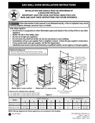
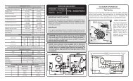
30" GAS SLIDE-IN RANGE INSTALLATION INSTRUCTIONS(Models with Sealed Top Burners)1. Cab<strong>in</strong>et ConstructionTo elim<strong>in</strong>ate the risk of cab<strong>in</strong>et burns andfire, do not have cab<strong>in</strong>et storage space above the <strong>range</strong>.If there is cab<strong>in</strong>et storage space above <strong>range</strong>, reduce riskby <strong>in</strong>stall<strong>in</strong>g a <strong>range</strong> hood that projects horizontally am<strong>in</strong>imum of 5" (12.7 cm) beyond the bottom of thecab<strong>in</strong>et.Countertop Preparation• The cooktop sides of the <strong>range</strong> fit over the cutout edgeof your countertop.• If you have a square f<strong>in</strong>ish (flat) countertop, nocountertop preparation is required. Cooktop sides laydirectly on edge of countertop.• Formed front-edged countertops must have moldededge shaved flat 3/4" (1.9 cm) from each front cornerof open<strong>in</strong>g (Figure 2).• Tile countertops may need trim cut back 3/4"(1.9cm) from each front corner and/or rounded edgeflattened (Figure 2).¾”(1.9 cm)M<strong>in</strong>.CutoutWidth31½”(81 cm)¾”(1.9 cm)Formed or tile countertoptrimmed ¾" (1.9 cm) back atfront corners of countertopopen<strong>in</strong>g.Figure 2• If the exist<strong>in</strong>g cutout width is greater than30-1/16" (76,4 cm), reduce the ¾" (1.9 cm)dimension.• Countertop must be level. Place a level on thecountertop, first side to side, then front to back. If thecountertop is not level, the <strong>range</strong> will not be level. Theoven must be level for satisfactory bak<strong>in</strong>g results.Cooktop sides of <strong>range</strong> fit over edges of countertopopen<strong>in</strong>g.2 3/16”(5.56 cm)• For exist<strong>in</strong>gcutout widthof 29" (73.7cm) (Figure 3):29”(73.7 cm)30”(76.2 cm) 31½”(81 cm)2. Provide an adequate Gas SupplyWhen shipped from the factory, this unit is designed tooperate on 4"(10,16 cm) water column (1.0 kPa) Natural<strong>gas</strong> manifold pressure. A convertible pressure regulator isconnected to the <strong>range</strong> manifold and MUST beconnected <strong>in</strong> series with the <strong>gas</strong> supply l<strong>in</strong>e. If LP/Propane conversion kit has been used, follow <strong>in</strong>structionsprovided with the kit for convert<strong>in</strong>g the pressureregulator to LP/Propane use.Care must be taken dur<strong>in</strong>g <strong>in</strong>stallation of <strong>range</strong> not toobstruct the flow of combustion and ventilation air.For proper operation, the maximum <strong>in</strong>let pressure to theregulator should be no more than 14"(35,56 cm) ofwater column pressure (3.5 kPa). The <strong>in</strong>let pressure tothe regulator must be at least 1" (.25 kPa) greater thanthe regulator manifold pressure sett<strong>in</strong>g. Examples: Ifregulator is set for natural <strong>gas</strong> 4"(10,16 cm) manifoldpressure, <strong>in</strong>let pressure must be at least 5"(12.60 cm); ifregulator has been converted for LP/Propane <strong>gas</strong>10"(25,4 cm) manifold pressure, <strong>in</strong>let pressure must beat least 11"(27,9 cm).Leak test<strong>in</strong>g of the appliance shall be conductedaccord<strong>in</strong>g to the <strong>in</strong>structions <strong>in</strong> step 4.The <strong>gas</strong> supply l<strong>in</strong>e should be ½" or ¾" I.D. (InteriorDiameter)3. Seal the open<strong>in</strong>gsSeal any open<strong>in</strong>gs <strong>in</strong> the wall beh<strong>in</strong>d the <strong>range</strong> and <strong>in</strong> thefloor under the <strong>range</strong> after <strong>gas</strong> supply l<strong>in</strong>e is <strong>in</strong>stalled.2 3/16”(5.56 cm)1¼”(3.2 cm)You must also clear2 3/16" (5.56 cm) ofmaterial from frontof countertop.1¼”(3.2 cm)Figure 3Formed or tile countertoptrimmed 1¼" (3.2 cm) back atfront corners of countertopopen<strong>in</strong>g.4