Bedienungsanleitung BETA PROLINE - Hebetechnik Ges.m.b.H.
Bedienungsanleitung BETA PROLINE - Hebetechnik Ges.m.b.H.
Bedienungsanleitung BETA PROLINE - Hebetechnik Ges.m.b.H.

You also want an ePaper? Increase the reach of your titles
YUMPU automatically turns print PDFs into web optimized ePapers that Google loves.
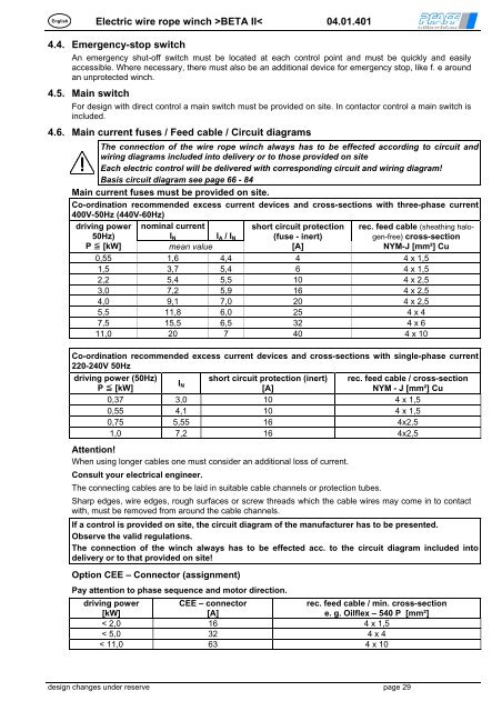
EnglishElectric wire rope winch ><strong>BETA</strong> II< 04.01.4014.4. Emergency-stop switchAn emergency shut-off switch must be located at each control point and must be quickly and easilyaccessible. Where necessary, there must also be an additional device for emergency stop, like f. e aroundan unprotected winch.4.5. Main switchFor design with direct control a main switch must be provided on site. In contactor control a main switch isincluded.4.6. Main current fuses / Feed cable / Circuit diagramsThe connection of the wire rope winch always has to be effected according to circuit andwiring diagrams included into delivery or to those provided on siteEach electric control will be delivered with corresponding circuit and wiring diagram!Basis circuit diagram see page 66 - 84Main current fuses must be provided on site.Co-ordination recommended excess current devices and cross-sections with three-phase current400V-50Hz (440V-60Hz)nominal currentI N I A / I Nshort circuit protection(fuse - inert)mean value[A]0,55 1,6 4,4 4 4 x 1,51,5 3,7 5,4 6 4 x 1,52,2 5,4 5,5 10 4 x 2,53,0 7,2 5,9 16 4 x 2,54,0 9,1 7,0 20 4 x 2,55,5 11,8 6,0 25 4 x 47,5 15,5 6,5 32 4 x 611,0 20 7 40 4 x 10driving power50Hz)P [kW]rec. feed cable (sheathing halogen-free)cross-sectionNYM-J [mm²] CuCo-ordination recommended excess current devices and cross-sections with single-phase current220-240V 50Hzdriving power (50Hz)short circuit protection (inert) rec. feed cable / cross-sectionIP [kW]N[A]NYM - J [mm²] Cu0,37 3,0 10 4 x 1,50,55 4,1 10 4 x 1,50,75 5,55 16 4x2,51,0 7,2 16 4x2,5Attention!When using longer cables one must consider an additional loss of current.Consult your electrical engineer.The connecting cables are to be laid in suitable cable channels or protection tubes.Sharp edges, wire edges, rough surfaces or screw threads which the cable wires may come in to contactwith, must be removed from around the cable channels.If a control is provided on site, the circuit diagram of the manufacturer has to be presented.Observe the valid regulations.The connection of the winch always has to be effected acc. to the circuit diagram included intodelivery or to that provided on site!Option CEE – Connector (assignment)Pay attention to phase sequence and motor direction.driving power[kW]CEE – connector[A]rec. feed cable / min. cross-sectione. g. Oilflex – 540 P [mm²]< 2,0 16 4 x 1,5< 5,0 32 4 x 4< 11,0 63 4 x 10design changes under reserve page 29