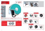

You also want an ePaper? Increase the reach of your titles
YUMPU automatically turns print PDFs into web optimized ePapers that Google loves.
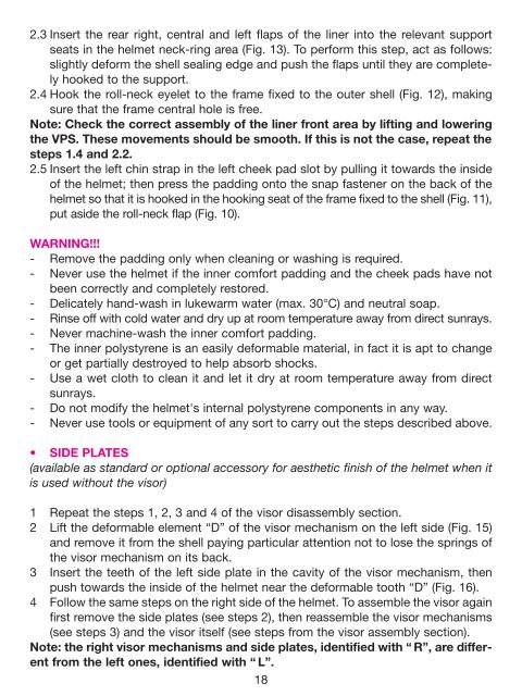
2.3 Insert the rear right, central and left flaps of the liner into the relevant support<br />
seats in the helmet neck-ring area (Fig. 13). To perform this step, act as follows:<br />
slightly deform the shell sealing edge and push the flaps until they are completely<br />
hooked to the support.<br />
2.4 Hook the roll-neck eyelet to the frame fixed to the outer shell (Fig. 12), making<br />
sure that the frame central hole is free.<br />
Note: Check the correct assembly of the liner front area by lifting and lowering<br />
the VPS. These movements should be smooth. If this is not the case, repeat the<br />
steps 1.4 and 2.2.<br />
2.5 Insert the left chin strap in the left cheek pad slot by pulling it towards the inside<br />
of the helmet; then press the padding onto the snap fastener on the back of the<br />
helmet so that it is hooked in the hooking seat of the frame fixed to the shell (Fig. 11),<br />
put aside the roll-neck flap (Fig. 10).<br />
WARNING!!!<br />
- Remove the padding only when cleaning or washing is required.<br />
- Never use the helmet if the inner comfort padding and the cheek pads have not<br />
been correctly and completely restored.<br />
- Delicately hand-wash in lukewarm water (max. 30°C) and neutral soap.<br />
- Rinse off with cold water and dry up at room temperature away from direct sunrays.<br />
- Never machine-wash the inner comfort padding.<br />
- The inner polystyrene is an easily deformable material, in fact it is apt to change<br />
or get partially destroyed to help absorb shocks.<br />
- Use a wet cloth to clean it and let it dry at room temperature away from direct<br />
sunrays.<br />
- Do not modify the helmet's internal polystyrene components in any way.<br />
- Never use tools or equipment of any sort to carry out the steps described above.<br />
• SIDE PLATES<br />
(available as standard or optional accessory for aesthetic finish of the helmet when it<br />
is used without the visor)<br />
1 Repeat the steps 1, 2, 3 and 4 of the visor disassembly section.<br />
2 Lift the deformable element “D” of the visor mechanism on the left side (Fig. 15)<br />
and remove it from the shell paying particular attention not to lose the springs of<br />
the visor mechanism on its back.<br />
3 Insert the teeth of the left side plate in the cavity of the visor mechanism, then<br />
push towards the inside of the helmet near the deformable tooth “D” (Fig. 16).<br />
4 Follow the same steps on the right side of the helmet. To assemble the visor again<br />
first remove the side plates (see steps 2), then reassemble the visor mechanisms<br />
(see steps 3) and the visor itself (see steps from the visor assembly section).<br />
Note: the right visor mechanisms and side plates, identified with “ R”, are different<br />
from the left ones, identified with “ L”.<br />
18