DSR 9900 PVR - Radix
DSR 9900 PVR - Radix
DSR 9900 PVR - Radix

Erfolgreiche ePaper selbst erstellen
Machen Sie aus Ihren PDF Publikationen ein blätterbares Flipbook mit unserer einzigartigen Google optimierten e-Paper Software.
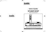
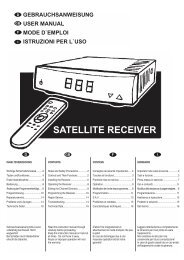
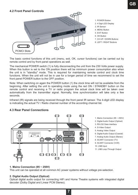
4.2 Front Panel Controls<br />
PCMCI Slots<br />
The basic control functions of this unit (menu, exit, OK, cursor functions) can be carried out by<br />
remote control and by front panel operations as well.<br />
The mechanical POWER switch (1) is fully disconnecting the unit from the 230 Volts power supply.<br />
When this button is set to the ON position there will be minimum power consumption also when<br />
the unit is in "standby" mode. This is required for maintaining remote control and clock time<br />
functions. When the unit will not be in use for a longer period of time we recommend to set the<br />
front panel POWER button to the OFF position.<br />
Note: When switching on again the POWER button (1) the clock time will not be available from the<br />
beginning. After setting the unit to operating mode using the red ON / STANDBY button on the<br />
remote control and receiving a TV or radio program the actual clock time will be taken over<br />
automatically from the transmitter signal. Normally, time synchronization will take only a few<br />
seconds.<br />
Infrared (IR) signals are being received through the front panel IR sensor. The 4-digit LED display<br />
is indicating the actual TV / Radio channel number of the according channel list.<br />
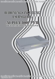
4.3 Rear Panel Connections<br />
1<br />
2 3<br />
4<br />
5<br />
6<br />
1. Mains Connection (95 ~ 250V)<br />
This unit can be operated at all common AC power systems without voltage pre-selection.<br />
7<br />
2. Digital Audio Output (Optical)<br />
Optical digital audio output for connecting HiFi and Home Theatre systems with integrated digital<br />
decoder (Dolby Digital and Linear PCM Stereo).<br />
8<br />
9<br />
7<br />
10<br />
11<br />
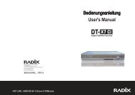
1. POWER Button<br />
2. 4 Digit LED Display<br />
3. IR Sensor<br />
4. MENU Button<br />
5. EXIT Button<br />
6. OK Button<br />
7. CH UP / DOWN Buttons<br />
8. LEFT / RIGHT Buttons<br />
1. Mains Connection (95 ~ 250V)<br />
2. Digital Audio Output (Optical)<br />
3. RS-232 Data Interface<br />
4. S-Video Output<br />
5. Analog Video Output<br />
6. Digital Audio Output (Coaxial)<br />
7. Analog Audio Output (Stereo)<br />
8. SCART Connector (TV)<br />
9. SCART Connector (VCR)<br />
10. LNB Input<br />
11. LNB Loop-Through Output<br />
GB