SDM-9220/9230 - Comtech EF Data
SDM-9220/9230 - Comtech EF Data
SDM-9220/9230 - Comtech EF Data

Create successful ePaper yourself
Turn your PDF publications into a flip-book with our unique Google optimized e-Paper software.
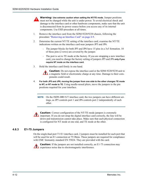
<strong>SDM</strong>-<strong>9220</strong>/<strong>9230</strong> Hardware Installation Guide<br />
4.6.3 E1-75 Jumpers<br />
Warning: Use extreme caution when setting the NT/TE mode. Jumper positions<br />
must not be changed while the unit is under power. To avoid electrical shock and<br />
damage to the interface card or other hardware components, make sure that the unit<br />
is disconnected from its power source before you access any of its internal<br />
components. Use ESD procedure at all times.<br />
1. Remove the interface card from the <strong>SDM</strong>-<strong>9220</strong>/<strong>9230</strong> chassis, following the<br />
procedure “Removing an Interface Card” on page 4-9.<br />
2. Determine the current NT/TE setting of the interface card; examine the NT/TE<br />
indications written on the interface card near jumpers JP5 and JP6.<br />
- The jumper blocks for both JP5 and JP6 have 15 pins in a 3x5 formation. 10<br />
of these pins (2 rows) are covered by the jumper.<br />
- The port is set to TE mode at the factory. If you are strapping a new interface<br />
card, you need to change the factory setting of jumpers JP5 and JP6 only if you<br />
require NT mode on the interface card.<br />
3. Hold the interface card firmly in one hand.<br />
Caution: Do not expose the interface card or the <strong>SDM</strong>-<strong>9220</strong>/<strong>9230</strong> unit to<br />
a magnetic field or electrostatic charge at any time. Damage to their components<br />
could result.<br />
4. For both JP5 and JP6, moving the jumper from one side to the other changes TE mode<br />
to NT, or NT mode to TE. Using needle-nosed pliers, move the jumpers to the pin<br />
positions required for your interface.<br />
NOTE: On the ISDN-BRI S/T interface card, the two jumpers can have different settings,<br />
as JP5 controls port 1 and JP6 controls port 2 independently of each<br />
other.<br />
Caution: Correct configuration of the NT/TE mode jumpers is extremely<br />
important. If you do not strap the digital interface card correctly, the line will be<br />
down and transmission cannot take place. Make sure that each physical connection<br />
is configured for NT mode at one end, and TE mode at the other.<br />
On the single/dual port T1/E1 interface card, 2 jumpers must be installed for each port that<br />
will be used for an E1 connection at 75 Ohms. These jumpers are required for compliance<br />
with EMC Immunity standard EN 55024. They are provided with the card.<br />
Caution: If the jumpers are not installed correctly, an E1-75 connection may<br />
experience noise due to electromagnetic interference.<br />
4-12 Memotec Inc.