SDM-9220/9230 - Comtech EF Data
SDM-9220/9230 - Comtech EF Data
SDM-9220/9230 - Comtech EF Data

You also want an ePaper? Increase the reach of your titles
YUMPU automatically turns print PDFs into web optimized ePapers that Google loves.
<strong>SDM</strong>-<strong>9220</strong>/<strong>9230</strong> Hardware Installation Guide<br />
Warning: Use extreme caution when setting the NT/TE mode. Jumpers must<br />
not be installed while the unit is under power. To avoid electrical shock and damage<br />
to the interface card or other hardware components, make sure that the unit is<br />
disconnected from its power source before you access any of its internal<br />
components. Also ensure that the RJ-48 to E1-75 dual BNC adaptor cable, or<br />
balun adaptor with RJ-45 to RJ-45 patch cable, has been disconnected from<br />
the digital port. Use ESD procedure at all times.<br />
1. Remove the T1/E1 interface card from the <strong>SDM</strong>-<strong>9220</strong>/<strong>9230</strong> chassis, following the<br />
procedure “Removing an Interface Card” on page 4-9.<br />
2. Hold the interface card firmly in one hand.<br />
Caution: Do not expose the interface card or the <strong>SDM</strong>-<strong>9220</strong>/<strong>9230</strong> unit to<br />
a magnetic field or electrostatic charge at any time. Damage to their components<br />
could result.<br />
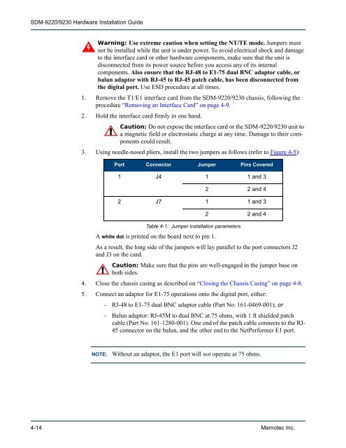
3. Using needle-nosed pliers, install the two jumpers as follows (refer to Figure 4-5):<br />
Port Connector Jumper Pins Covered<br />
1 J4 1 1 and 3<br />
2 2 and 4<br />
2 J7 1 1 and 3<br />
2 2 and 4<br />
Table 4-1: Jumper installation parameters<br />
A white dot is printed on the board next to pin 1.<br />
As a result, the long side of the jumpers will lay parallel to the port connectors J2<br />
and J3 on the card.<br />
Caution: Make sure that the pins are well-engaged in the jumper base on<br />
both sides.<br />
4. Close the chassis casing as described on “Closing the Chassis Casing” on page 4-8.<br />
5. Connect an adaptor for E1-75 operations onto the digital port, either:<br />
- RJ-48 to E1-75 dual BNC adaptor cable (Part No. 161-0469-001), or<br />
- Balun adaptor: RJ-45M to dual BNC at 75 ohms, with 1 ft shielded patch<br />
cable (Part No. 161-1280-001). One end of the patch cable connects to the RJ-<br />
45 connector on the balun, and the other end to the NetPerformer E1 port.<br />
NOTE: Without an adaptor, the E1 port will not operate at 75 ohms.<br />
4-14 Memotec Inc.