Untitled - Future Pipe Industries
Untitled - Future Pipe Industries
Untitled - Future Pipe Industries

You also want an ePaper? Increase the reach of your titles
YUMPU automatically turns print PDFs into web optimized ePapers that Google loves.
5.6: <strong>Pipe</strong>s with locked joints<br />
For some underground applications, pipes might be provided with a restrained mechanical gasketed joint. Typical applications<br />
are pipes laid in deep slopes, or where thrust blocks can not be used, and for pipes used as well-casings. In this case,<br />
special pipe and Reka couplings (or special Bell/Spigot joints), designed to resist the high longitudinal stresses, are provided.<br />
One locking key (strip), or more, is inserted into the joint to restrain and lock the two-pipe sections jointed. The joint<br />
assembly shall be done as per the following recommendations:<br />
• The joint should be assembled in such a way that the position of the hole in the socket (coupling) allows the locking strip<br />
to be inserted easily.<br />
• Lubricate lightly the first 6-8” section of the locking key (strip).<br />
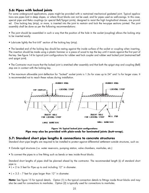
• The beveled end of the locking key should be resting against the inside surface of the socket or coupling when inserting.<br />
The insertion should be made using a plastic hammer or a piece of wood to tap the key until it resists against the first part of<br />
the key. See figure 14 for typical joint configurations for rubber seal lock coupler and rubber seal locked joint (restrained bell<br />
and spigot joint).<br />
• The Contractor must insure that the locked joint is stretched after assembly and that both the spigot stop and coupling (Bell)<br />
stop are in contact with the locking key.<br />
• The maximum allowable joint deflection for “locked” socket joints is 1.5o for sizes up to 24” and 1o for larger sizes. It<br />
is recommended not to reach these values during installation.<br />
Figure 14: Typical locked joint configurations<br />
<strong>Pipe</strong> may also be provided with plain-ends for laminated joints (butt-wrap).<br />
5.7: Standard short pipe lengths & connections to concrete structures<br />
Standard short pipe lengths are required to be installed to protect against differential settlement outside structures, such as:<br />
• Outside rigid structures (i.e. water reservoirs, pumping station, valve chambers, manholes, etc.)<br />
• To connect the pipes to a line fitting such as bends or tees inside thrust blocks.<br />
Standard short lengths of pipes shall be planned ahead by the contractor. The recommended length (L) of standard short<br />
pipe is:<br />
•L=2to 3 feet for <strong>Pipe</strong> up to and including 12” in diameter.<br />
• L = 3.5 – 7 feet for pipe larger than 12” in diameter.<br />
Note: See figure 15 for typical details. Option (1) is the typical connection details to fittings inside thrust blocks and may<br />
also be used for connections to manholes. Option (2) is typically used for connections to manholes.<br />
25