Untitled - Future Pipe Industries
Untitled - Future Pipe Industries
Untitled - Future Pipe Industries

Create successful ePaper yourself
Turn your PDF publications into a flip-book with our unique Google optimized e-Paper software.
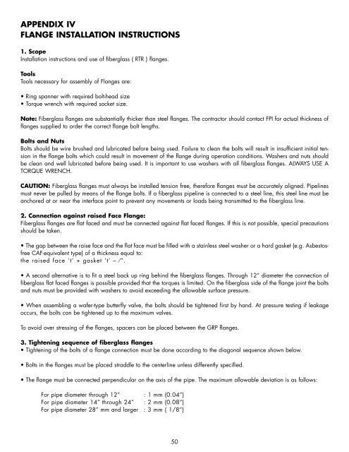
APPENDIX IV<br />
FLANGE INSTALLATION INSTRUCTIONS<br />
1. Scope<br />
Installation instructions and use of fiberglass ( RTR ) flanges.<br />
Tools<br />
Tools necessary for assembly of Flanges are:<br />
• Ring spanner with required bolt-head size<br />
• Torque wrench with required socket size.<br />
Note: Fiberglass flanges are substantially thicker than steel flanges. The contractor should contact FPI for actual thickness of<br />
flanges supplied to order the correct flange bolt lengths.<br />
Bolts and Nuts<br />
Bolts should be wire brushed and lubricated before being used. Failure to clean the bolts will result in insufficient initial tension<br />
in the flange bolts which could result in movement of the flange during operation conditions. Washers and nuts should<br />
be clean and well lubricated before being used. It is important to use washers with all fiberglass flanges. ALWAYS USE A<br />
TORQUE WRENCH.<br />
CAUTION: Fiberglass flanges must always be installed tension free, therefore flanges must be accurately aligned. <strong>Pipe</strong>lines<br />
must never be pulled by means of the flange bolts. If a fiberglass pipeline is connected to a steel line, this steel line must be<br />
anchored at or near the interface point to prevent any movements or loads being transmitted to the fiberglass line.<br />
2. Connection against raised Face Flange:<br />
Fiberglass flanges are flat faced and must be connected against flat faced flanges. If this is not possible, special precautions<br />
should be taken.<br />
• The gap between the raise face and the flat face must be filled with a stainless steel washer or a hard gasket (e.g. Asbestosfree<br />
CAF-equivalent type) of a thickness equal to:<br />
the raised face ‘t’ + gasket ‘t’ – ⁄”.<br />
• A second alternative is to fit a steel back up ring behind the fiberglass flanges. Through 12” diameter the connection of<br />
fiberglass flat faced flanges is possible provided that the torques is limited. On the fiberglass side of the flange joint the bolts<br />
and nuts must be provided with washers to avoid exceeding the allowable surface pressure.<br />
• When assembling a wafer-type butterfly valve, the bolts should be tightened first by hand. At pressure testing if leakage<br />
occurs, the bolts can be tightened up to the maximum valves.<br />
To avoid over stressing of the flanges, spacers can be placed between the GRP flanges.<br />
3. Tightening sequence of fiberglass flanges<br />
• Tightening of the bolts of a flange connection must be done according to the diagonal sequence shown below.<br />
• Bolts in the flanges must be placed straddle to the centerline unless differently specified.<br />
• The flange must be connected perpendicular on the axis of the pipe. The maximum allowable deviation is as follows:<br />
For pipe diameter through 12” : 1 mm (0.04”)<br />
For pipe diameter 14” through 24” : 2 mm (0.08”)<br />
For pipe diameter 28” mm and larger : 3 mm ( 1/8”)<br />
50