Untitled - Future Pipe Industries
Untitled - Future Pipe Industries
Untitled - Future Pipe Industries

Create successful ePaper yourself
Turn your PDF publications into a flip-book with our unique Google optimized e-Paper software.
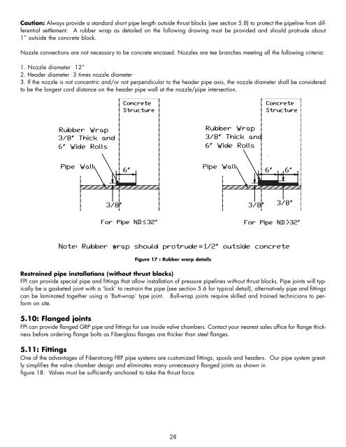
Caution: Always provide a standard short pipe length outside thrust blocks (see section 5.8) to protect the pipeline from differential<br />
settlement. A rubber wrap as detailed on the following drawing must be provided and should protrude about<br />
1” outside the concrete block.<br />
Nozzle connections are not necessary to be concrete encased. Nozzles are tee branches meeting all the following criteria:<br />
1. Nozzle diameter 12”<br />
2. Header diameter 3 times nozzle diameter<br />
3. If the nozzle is not concentric and/or not perpendicular to the header pipe axis, the nozzle diameter shall be considered<br />
to be the longest cord distance on the header pipe wall at the nozzle/pipe intersection.<br />
Figure 17 : Rubber warp details<br />
Restrained pipe installations (without thrust blocks)<br />
FPI can provide special pipe and fittings that allow installation of pressure pipelines without thrust blocks. <strong>Pipe</strong> joints will typically<br />
be a gasketed joint with a ‘lock’ to restrain the pipe (see section 5.6 for typical detail), alternatively pipe and fittings<br />
can be laminated together using a ‘Butt-wrap’ type joint. Bull-wrap joints require skilled and trained technicians to perform<br />
on site.<br />
5.10: Flanged joints<br />
FPI can provide flanged GRP pipe and fittings for use inside valve chambers. Contact your nearest sales office for flange thickness<br />
before ordering flange bolts as Fiberglass flanges are thicker than steel flanges.<br />
5.11: Fittings<br />
One of the advantages of Fiberstrong FRP pipe systems are customized fittings, spools and headers. Our pipe system greatly<br />
simplifies the valve chamber design and eliminates many unnecessary flanged joints as shown in<br />
figure 18. Valves must be sufficiently anchored to take the thrust force.<br />
28