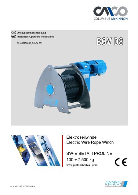
Elektroseilwinde Electric Wire Rope Winch SW-E ... - Pfaff-silberblau
Elektroseilwinde Electric Wire Rope Winch SW-E ... - Pfaff-silberblau
Elektroseilwinde Electric Wire Rope Winch SW-E ... - Pfaff-silberblau

Create successful ePaper yourself
Turn your PDF publications into a flip-book with our unique Google optimized e-Paper software.
D Original Betriebsanleitung<br />
GB Translated Operating Instructions<br />
Nr. 036150036_Ed.-04.2011<br />
04.01.401_PDF_01.09.2011 / UD<br />
<strong>Elektroseilwinde</strong><br />
<strong>Electric</strong> <strong>Wire</strong> <strong>Rope</strong> <strong>Winch</strong><br />
<strong>SW</strong>-E BETA II PROLINE<br />
100 ÷ 7.500 kg<br />
www.pfaff-<strong>silberblau</strong>.com
D<br />
GB<br />
<strong>Elektroseilwinde</strong> BETA II_BGV D8<br />
<strong>Electric</strong> <strong>Wire</strong> <strong>Rope</strong> <strong>Winch</strong> BETA II_BGV D8<br />
Inhaltsverzeichnis / Summary / Index<br />
Deutsch<br />
04.01.401<br />
1 Unfallverhütung .............................................................................................................3<br />
2 Technische Daten .........................................................................................................5<br />
3 Einbauanleitung.............................................................................................................6<br />
4 Elektro-Installation.........................................................................................................8<br />
5 Bedienung ...................................................................................................................13<br />
6 Inspektions- und Wartungsanleitung ...........................................................................15<br />
7 Betriebsstörungen und ihre Ursachen .........................................................................19<br />
8 Sonderausstattung (werden nur bei gesonderter Bestellung geliefert)........................20<br />
9 Sonderausstattung ( in Standard nicht enthalten) .......................................................21<br />
English<br />
1 Prevention of accidents ...............................................................................................22<br />
2 Technical Data ............................................................................................................24<br />
3 Mounting Instructions ..................................................................................................25<br />
4 <strong>Electric</strong> Installation ......................................................................................................27<br />
5 Operation.....................................................................................................................32<br />
6 Inspection- and Maintenance Instructions ...................................................................34<br />
7 Operating failures and their causes.............................................................................38<br />
8 Special equipment (will only be delivered by special order) ........................................39<br />
9 Special equipment ( not included in standard design) .................................................40<br />
Francais ¸<br />
Spezifische technische Daten / Specific technical data / Donnés techniques spécifiques .........41<br />
Elektroschaltpläne / Circuit diagrams / Plans des montage éleéctrique .....................................49<br />
Ersatzteilliste / Spare parts list / Liste des pièces détachées / Lista dei pezzi di ricambio ........68<br />
Einbauerklärung / Declaration of incorporation / Déclaration d'incorporation .............................74<br />
EG-Konformitätserklärung / EC-Declaration of Conformity / Déclaration "CE" de Conformité ...75<br />
technische Änderungen vorbehalten design changes under reserve changements techniques sous réserve 2
Deutsch<br />
<strong>Elektroseilwinde</strong> BETA II 04.01.401<br />
Vor Inbetriebnahme die Betriebsanleitung aufmerksam lesen!<br />
Sicherheitshinweise beachten!<br />
Dokument aufbewahren!<br />
1 Unfallverhütung<br />
1.1 Bestimmungsgemäße Verwendung<br />
Die <strong>Elektroseilwinde</strong> >BETA< ist eine motorbetriebene Seilwinde für Konsolbefestigung zum<br />
Heben und Senken von Lasten.<br />
Nicht geeignet für Einsatz in explosionsgefährdeten Räumen.<br />
Nicht geeignet für Einsatz in aggressiver Umgebung.<br />
Änderungen an der Seilwinde, sowie das Anbringen von Zusatzgeräten, sind nur mit<br />
unserer ausdrücklichen schriftlichen Genehmigung erlaubt.<br />
Technische Daten und Funktionsbeschreibung beachten!<br />
1.2 Unfallverhütungsvorschriften<br />
Es sind jeweils die im Einsatzland gültigen Vorschriften zu beachten. 1)<br />
in Deutschland z.Zt.:<br />
EG Richtlinie 2006/42/EG<br />
BGV D 8 Winden- Hub- und Zuggeräte<br />
BGV D 6 Krane<br />
BGR 500 Kap. 2.8 Lastaufnahmeeinrichtungen im Hebezeugbetrieb<br />
DIN EN 13155 Lose Lastaufnahmemittel<br />
EN 14492-1; EN 14492-2 Kraftbetriebene Hubwerke<br />
DIN 15020 Blatt 1 und Blatt 2<br />
EN 60204 T1, El. Ausrüstung von Maschinen<br />
EN 60204 T32, El. Ausrüstung von Maschinen-Hebezeuge (VDE 0100 T726)<br />
FEM 9.661, ISO 4308/1, ISO 4301/1<br />
FEM 9.775, FEM 9.511<br />
1) in der jeweils gültigen Fassung<br />
1.3 Sicherheitshinweise<br />
Bedienung, Montage und Wartung nur durch:<br />
Beauftragtes, qualifiziertes Personal<br />
(Definition für Fachkräfte nach IEC 364) Qualifiziertes Personal sind Personen, die aufgrund ihrer Ausbildung, Erfahrung,<br />
Unterweisung sowie Kenntnisse über einschlägige Normen und Bestimmungen, Unfallverhütungsvorschriften<br />
und Betriebsverhältnisse von den für die Sicherheit der Anlage Verantwortlichen berechtigt worden sind, die jeweils<br />
erforderliche Tätigkeit auszuführen und dabei mögliche Gefahren erkennen und vermeiden können.<br />
Das Befördern von Personen, sowie der Aufenthalt im Gefahrenbereich ist verboten.<br />
Aufenthalt unter gehobener Last verboten.<br />
Nie in bewegliche Teile greifen.<br />
Mängel sind sofort sachkundig zu beheben.<br />
1.3.1 Die Last<br />
� nie in gehobenen Zustand unbeaufsichtigt schweben lassen<br />
� nie schaukeln lassen<br />
� darf nie ins Seil fallen<br />
� nie in Bereiche bewegen, die nicht eingesehen werden können. Gesamter Hubbereich muss einschaubar<br />
sein.<br />
1.3.2 Das Seil<br />
� dient nur zum Heben und Senken bzw. Ziehen diverser Lasten und darf zu nichts anderem<br />
verwendet werden<br />
� Bordscheibenüberstand muss mind. das 1,5-fache des Seildurchmessers betragen,<br />
� regelmäßig nach DIN 15020 Bl. 2 prüfen und warten<br />
� mind. 3 Seilwindungen müssen bei Last in unterster Stellung immer auf der Trommel bleiben<br />
� zul. Seilablenkungswinkel (siehe Bild) � bei Standardseil �3°; � bei Spezialseil �1,5°<br />
� Bei ungeführten Lasten drehungsfreie Seile verwenden<br />
� nicht in Seileinlauf greifen<br />
�3°<br />
�1,5°<br />
�3°<br />
�1,5°<br />
� nur mit Schutzhandschuhen anfassen.<br />
� schlaffes Seil vorsichtig an die Last heranführen<br />
3. 2. 1.<br />
technische Änderungen vorbehalten design changes under reserve changements techniques sous réserve 3
Deutsch<br />
<strong>Elektroseilwinde</strong> BETA II 04.01.401<br />
1.3.3 Die Winde<br />
Tragfähigkeit entsprechend der aufgewickelten Seillage nicht überschreiten.<br />
Vor Inbetriebnahme durch Sachkundigen prüfen:<br />
� Hubgerät<br />
� Überlastschutzeinrichtung (falls vorhanden)<br />
� Tragkonstruktion<br />
� Tragmittel<br />
� Einbau<br />
1.4 Elektroteile<br />
Elektroanschluss bzw. Reparaturen an Elektroteilen dürfen nur von ausgebildeten Elektrofachleuten<br />
ausgeführt werden.<br />
Die Sicherheitsrichtlinien und Normen des Elektrohandwerkes sind zu beachten.<br />
Arbeiten an der Elektroanlage dürfen nur bei freigeschalteter Stromzuführung erfolgen.<br />
1.5 Tägliche Prüfungen<br />
� Funktionsschalter AUF – AB<br />
� Endschalter (falls vorh.)<br />
� Not-Aus-Einrichtung<br />
� Hauptschalter<br />
� El. Überlastsicherung (falls<br />
vorhanden).Bei Hublast ab 1.000 kg<br />
zwingend erforderlich.<br />
1.6 Das Lastaufnahmemittel<br />
� Steuerung<br />
� Bremsenfunktion (Motorbremse)<br />
� Zustand des Seiles und Lastaufnahmemittels<br />
� Tragkonstruktion<br />
� Tragmittel<br />
� auf ausreichende Tragfähigkeit achten<br />
� Lasthaken müssen Sicherheitsklappen haben<br />
� Lasthaken muss vorschriftsmäßig mit Seilkausche und Pressklemme mit dem<br />
Seil verpresst sein.<br />
� die Last richtig befestigen<br />
� Windenseil nicht als Anschlagmittel verwenden<br />
1.7 Hinweise für Seilendbefestigungen<br />
Seilaufhängung und Seilbefestigung: Das Ende eines neu aufgelegten Seiles muss so<br />
ausgelegt sein, dass dauerhaft sichergestellt ist, dass das Seilgefüge nicht locker wird.<br />
Die Seilendverbindung ist regelmäßig zu prüfen.( Drahtbrüche- Korrosion -Risse- in<br />
der Hülse- Lockern der Klemmschrauben usw.)<br />
Als Seilendverbindungen dürfen nur verwendet werden<br />
�Aluminiumpressverbindungen DIN 3093<br />
�Spleißverbindungen DIN 3089(nicht bekleidet)<br />
�Seilschlösser<br />
Seilschlösser (ähnl. DIN 43148); Seilverbindung mit<br />
zus. Seilklemme nach DIN 1142 gesichert<br />
A B<br />
Nur im Aufzugbau<br />
zulässig<br />
Das freie Seilende ist gegen Durchziehen zu sichern.<br />
Die Sicherungsart C ist für Hebezeuge und Lastaufnahmeeinrichtungen nicht erlaubt!<br />
� Drahtseilklemmen nach DIN 1142 dürfen als Seilendverbindung im<br />
Hebezeugbetrieb nicht eingesetzt werden,<br />
Aluminiumpressverbindungen<br />
DIN 3093<br />
Spleißverbindungen<br />
DIN 3089(nicht bekleidet)<br />
Mindestens 1x jährlich UVV Prüfung durch Sachkundigen durchführen.<br />
Inspektions- und Wartungsintervalle unbedingt einhalten.<br />
Nur original Zubehör- und Ersatzteile verwenden, sichere Funktion ansonsten nicht gewährleistet.<br />
technische Änderungen vorbehalten design changes under reserve changements techniques sous réserve 4<br />
C
Deutsch<br />
<strong>Elektroseilwinde</strong> BETA II 04.01.401<br />
2 Technische Daten<br />
Spezifische Technische Daten siehe Tabelle ab Seite 41 bzw. beigefügtes Datenblatt.<br />
2.1 Funktionsbeschreibung<br />
Bei der <strong>Elektroseilwinde</strong> >BETA< handelt es sich um Trommelwinden mit Stirnradgetriebe (BG 1 - 5)<br />
bzw. mit Schneckengetriebe (BG M 0)<br />
Die Last wird durch eine elektromagnetisch lüftende Scheibenbremse in jeder Stellung gehalten.<br />
Die <strong>Elektroseilwinde</strong> kann mit Direktsteuerung, [Drucktastern AUF-AB und NOT-AUS] oder mit einer<br />
Elektroschützensteuerung [mit eingebauten Drucktastern AUF-AB, NOT-AUS Taster / Schalter, Hauptschalter]<br />
geliefert werden.<br />
Ab 1000 kg Hublast ist eine Schützensteuerung mit elektronischem Überlastschutz erforderlich.<br />
Falls erforderlich sind Endschalter vorzusehen.<br />
Bei Verwendung von Endschaltern muss die Seilwinde mit Schützensteuerung ausgerüstet werden. Endschalter<br />
können bauseitig, bzw. mit angebautem Getriebeendschalter, ausgeführt sein.<br />
2.2 Allgemeine technische Daten<br />
Baugröße M0 P 1-5 C 1-5 E 1-5<br />
Triebwerkgruppe nach DIN 15020 1Bm 2m 1Am 1Bm<br />
Betriebsart (gem. VDE 530) S3 - 40%<br />
max. Schaltungen pro Stunde 120<br />
Schutzart IP 54 / 55<br />
empf. Seil:<br />
� DIN 3060 FE-znk 1770 sZ-spa<br />
� DIN 3064 FE-znk 1770 sZ-spa<br />
� DIN 3069 SE-znk 1960 sZ-spa<br />
� DIN 3069 SE-znk 2160 sZ-spa<br />
� Spezialseile auf Anfrage lieferbar<br />
geeignet für Umgebungstemperatur -20°C÷ +40°C<br />
<strong>Elektroseilwinde</strong> >BETA< mit 1 Geschwindigkeit für Drehstrom<br />
Motoranschluss (Standard) Motor:<br />
bei 50 Hz 60 Hz 1) Anschlussspannung U ~<br />
380-420 V �5% 50 Hz<br />
440-460 V �5% 60 Hz<br />
P � 3,0 kW 3,3 kW Y Bremse: Anschluss über Einweggleichrichter<br />
P � 3,0 kW 3,3 kW � Spulenspannung U - 170 ÷ 200 V DC<br />
<strong>Elektroseilwinde</strong> >BETA< mit 2 Geschwindigkeiten<br />
Motoranschluss bei 50 Hz Y / Y<br />
Motor: Bremse: Anschluss über Einweggleichrichter<br />
Anschlussspannung U ~ 380-420 V �5% 50 Hz Spulenspannung U - 170 ÷ 200 V DC<br />
<strong>Elektroseilwinde</strong> >BETA< mit 1 Geschwindigkeit und Einphasenwechselstrom<br />
Motoranschluss Einphasenwechselstrom<br />
Motor: Bremse: Anschluss über Einweggleichrichter<br />
Anschlussspannung U ~ 220-240 V �5% 50 Hz Spulenspannung U - 92 ÷ 110 V DC<br />
1) Vor Inbetriebnahme siehe 4.3 Seite 9<br />
Schalldruckpegel<br />
Der max. Schalldruckpegel [dB(A)], in Abhängigkeit<br />
von der Antriebsleistung, ist dem Diagramm<br />
zu entnehmen.<br />
mechanische Leistung / driving power [kW]<br />
technische Änderungen vorbehalten design changes under reserve changements techniques sous réserve 5<br />
Schalldruckpegel / sound level [dB(A)]
Deutsch<br />
<strong>Elektroseilwinde</strong> BETA II 04.01.401<br />
2.3 Hauptabmessungen<br />
Für detaillierte Angaben bitte Maßbild anfordern<br />
BG 1 - 5<br />
BG M 0<br />
BG A B ØC D E G<br />
[mm] [mm] [mm] [mm] [mm] [mm]<br />
M 0 185 170 12 5 185 200<br />
1 215 300 13,5 6 325 340<br />
1.5 215 300 13,5 6 325 340<br />
2 270 400 18 8 444 465<br />
3 320 510 22 10 547 570<br />
3.5 320 510 22 10 547 570<br />
4 380 660 26 12 687 720<br />
5 430 800 34 15 844 882<br />
3 Einbauanleitung<br />
3.1 Montage:<br />
BEACHTE:<br />
� Nach Entfernen der Transporthölzer kann die Winde in Richtung Motor<br />
kippen, deswegen muss die Winde bei der Montage gegen Kippen<br />
gesichert werden.<br />
� Krananhängepunkte beachten! (nicht bei BG M 0)<br />
� Anbaukonstruktionen für max. Kräfte auslegen<br />
(Stoßfaktoren gem. DIN 15018 sind zu berücksichtigen)<br />
� unbedingt auf ebene Anschraubfläche achten.<br />
� Winde nur mittels Qualitätsschrauben befestigen.<br />
� Schrauben gleichmäßig anziehen.<br />
� Schrauben sichern<br />
� auf unbehinderten Seilablauf achten<br />
3.2 Mechanische Befestigung:<br />
Krananhängepunkte<br />
Baugröße M0 1 1.5 2 3 3.5 4 5<br />
Schrauben M10 M 12 M 12 M 16 M 20 M 20 M 24 M 30<br />
Güteklasse min. 8.8<br />
Anzahl der Schrauben 4 4 4 4 4 4 4 4<br />
Anziehmoment [Nm] 40 70 70 170 340 340 590 1200<br />
technische Änderungen vorbehalten design changes under reserve changements techniques sous réserve 6<br />
Transporthölzer
Deutsch<br />
<strong>Elektroseilwinde</strong> BETA II 04.01.401<br />
3.3 Einbaulagen<br />
Die Seilwinden können in verschiedenen Lagen eingebaut werden.<br />
Entlüftungs-, Ölablass- und Ölstandsschraube gem. nachstehenden Abb.<br />
Bei BG 1 ist eine Entlüftungsschraube nicht erforderlich.<br />
Bei BG M 0 ist keine Änderung der Entlüftungs-, Ölablass- und Ölstandsschraube erforderlich. Getriebe<br />
lebensdauergeschmiert. Für alle Einbaulagen geeignet.<br />
Auf Ölfüllmenge achten! (siehe Tabelle)<br />
H - 01<br />
H - 03<br />
Hauptgetriebe<br />
3.4 Ölfüllmenge<br />
Entlüftungsschraube<br />
Ölablassschraube<br />
Ölstandsschraube<br />
Ölauge (falls vorhanden)<br />
H - 02<br />
H - 04<br />
Entlüftungsschraube<br />
Ölstandsschraube<br />
Ölablassschraube<br />
Bei einigen Seilwinden ist dem Hauptgetriebeantrieb ein Stirnradgetriebe<br />
vorgesetzt.<br />
Das vorgesetzte Stirnradgetriebe muss bei Veränderung der Einbaulage<br />
wie dargestellt angebaut werden.<br />
FZ = 2-stufige Getriebe<br />
FD = 3-stufige Getriebe<br />
Getriebeart FZ FD FZ FD FZ FD FZ FD<br />
Einbaulage<br />
BG H - 01 H - 02 H - 03 H - 04<br />
M0 [l] ca. Schneckengetriebe lebensdauergeschmiert<br />
1 [l] ca. 0,7 0,9 0,6 0,6 0,7 0,7 0,6 0,7<br />
1.5 [l] ca. 1,6 2,0 1,0 0,9 1,3 1,3 1,3 1,3<br />
2 [l] ca. 2,5 3,3 2,3 2,3 2,4 2,4 2,3 2,3<br />
3 [l] ca. 4,5 6,3 5,0 5,0 4,8 4,7 4,6 4,7<br />
3.5 [l] ca. 7,4 10,6 (0,5*) 9,2 10,6 (0,5*) 8,4 8,2(0,5*) 8,1 8,2<br />
4 [l] ca. 13,8 16,8 (1,0*) 13,7 13,5 (1,0*) 15,5 15,2 (1,0*) 14,8 14,8 (1,0*)<br />
5 [l] ca. 32,8 44,0 (1,7*) 30,0 28,8 (1,7*) 37,0 36,0 (1,7*) 35,8 35,8 (1,7*)<br />
* Ölmenge, vorgesetztes Stirnradgetriebe (falls vorh.)<br />
3.5 Drahtseileinlauf<br />
180°<br />
90°<br />
Seileinlauf - rechts 270°<br />
technische Änderungen vorbehalten design changes under reserve changements techniques sous réserve 7<br />
0°<br />
Seileinlauf - links<br />
0°<br />
90°<br />
270°<br />
180°
Deutsch<br />
<strong>Elektroseilwinde</strong> BETA II 04.01.401<br />
3.6 Drahtseilbefestigung<br />
ACHTUNG:<br />
Die Seilwinde hat serienmäßig zwei Seilbefestigungen. Das Seil kann wahlweise, je nach Bedarf, an linker<br />
oder rechter Bordscheibe befestigt werden. Die Seilbefestigung erfolgt mit 2 bzw. 3 Klemmschrauben.<br />
Auf richtige Polung des Antriebsmotors achten!<br />
BG M 0 und Sonderausführung<br />
(mehrseilig)<br />
2<br />
� Drahtseil unter Berücksichtigung<br />
des Seileinlaufs einführen<br />
� Klemmschrauben � anziehen.<br />
BG 1 – 5 Standard (einseilig)<br />
1<br />
3<br />
2<br />
4<br />
� Drahtseil � unter Berücksichtigung<br />
des Seileinlaufes in Seilklemmenbohrung<br />
� einführen.<br />
� Klemmschrauben � anziehen<br />
� Drahtseilende � muss aus der<br />
Seilklemme � herausschauen<br />
Anziehmomente der Klemmschrauben �<br />
Seildurchmesser 4 4; 5; 6 7; 8; 9 10 11; 12; 13; 14 15; 16; 17; 18 19; 20; 21; 22; 23 24<br />
Klemmschrauben M 5 M 6 M 8 M 10 M 12 M 16 M 20 M 24<br />
Anziehmomente [Nm] 4,8 8,5 20 40 70 170 340 590<br />
Die technischen Daten bezüglich Mindestbruchfestigkeit sind entsprechend Typenschild bzw.<br />
Hinweis in der Bedienungsanleitung einzuhalten!<br />
Bei ungeführten Lasten, vor allem bei Einseilaufhängung, muss das Seildrehverhalten bei der<br />
Auswahl der Seilart berücksichtigt werden.<br />
Je nach gewähltem Seildurchmesser bzw. nach Seillänge, ist bei ungeführten Lasten ein<br />
drehungsfreies bzw. drehungsarmes Drahtseil zu verwenden.<br />
Seillänge so bemessen, dass in unterster Laststellung mind. 3 Seilwindungen auf der Trommel<br />
verbleiben.<br />
Max. Seillänge beachten.<br />
Bei Lieferung der Seilwinde ohne Elektrosteuerung bzw. bauseitiger Steuerungserstellung,<br />
sind die Angaben über Elektrosteuerung, Bedienelemente und Bedienung<br />
als Projektierungshinweise zu betrachten.<br />
Der Hersteller der Gesamtanlage führt eine Gefährdungsanalyse gem. EN 1050<br />
durch und stellt Benutzerhinweise und technische Dokumentationen für die<br />
Gesamtanlage eigenverantwortlich zur Verfügung.<br />
4 Elektro-Installation<br />
Arbeiten an der Elektroanlage dürfen nur:<br />
� bei freigeschalteter Stromzuführung erfolgen<br />
� von ausgebildeten Fachkräften des Elektrohandwerks durchgeführt werden.<br />
Die Sicherheitsrichtlinien und Normen des Elektrohandwerkes sind zu beachten.<br />
In Deutschland gelten hierfür die VDE-Richtlinien.<br />
4.1 Einbauhinweis für Schützensteuerung<br />
Die Schützensteuerung darf nur mit vertikal stehenden Schützen befestigt werden.<br />
Max. Schräglage 22,5°.<br />
Zum Ansteuern der Winde ist eine Elektrosteuerung erforderlich.<br />
Die <strong>Elektroseilwinde</strong> wird je nach Auftrag mit Schützensteuerung oder mit Direktsteuerung geliefert.<br />
Sollte die <strong>Elektroseilwinde</strong> ohne Steuerung geliefert und die Elektrosteuerung bauseitig erstellt werden,<br />
sind nachstehende Hinweise sowie die technischen Richtlinien des Verwendungslandes zu beachten.<br />
z.B.: EN 60204 T1, T32.<br />
Die Verantwortung liegt beim Hersteller des Steuergerätes.<br />
technische Änderungen vorbehalten design changes under reserve changements techniques sous réserve 8
Deutsch<br />
<strong>Elektroseilwinde</strong> BETA II 04.01.401<br />
4.2 Hinweis EMV<br />
Die <strong>Elektroseilwinde</strong> mit Steuerung ist ausgelegt für Industriebetrieb.<br />
Die Norm für elektromagnetische Störemissionen (EN DIN 50081-2), wird bis max. 5 Schaltvorgänge/min<br />
erfüllt.<br />
Für Anwendung in Verbindung mit elektronischen Schaltkreisen oder Dergleichen bzw. bei mehr als 5<br />
Schaltvorgängen/min. sind zusätzliche EMV Maßnahmen (Netzfilter) durchzuführen (bauseitig bzw. als<br />
Option lieferbar).<br />
4.3 Anschluss an Drehstromnetz<br />
Der im Motorklemmkasten befindliche Anschlussplan ist zu beachten.<br />
4.3.1 Motoranschluss-Klemmbrett 3 Phasen Drehstrom 1 Geschwindigkeit (Verkettung √3)<br />
Stern-Schaltung<br />
Y<br />
Dreieck-Schaltung<br />
Δ<br />
W2 U2 V2<br />
U1 V1 W1<br />
L1 L2 L3<br />
W2 U2 V2<br />
U1 V1 W1<br />
L1 L2 L3<br />
f =50 Hz:<br />
Motorleistung � 3,0 kW<br />
Spannung: 380 ÷ 420 V<br />
f =60 Hz:<br />
Motorleistung � 3,6 kW<br />
Spannung:440 ÷ 460 V<br />
f = 50 Hz:<br />
Motorleistung � 3,0 kW<br />
Spannung: 380 ÷ 420 V<br />
f = 60 Hz:<br />
Motorleistung � 3,6 kW<br />
Spannung: 440 ÷ 460 V<br />
4.3.2 Motoranschluss-Klemmbrett 3 Phasen-Drehstrom 1 Geschwindigkeit UL-R (CSA) NEMA<br />
230 V<br />
460 V<br />
technische Änderungen vorbehalten design changes under reserve changements techniques sous réserve 9
Deutsch<br />
<strong>Elektroseilwinde</strong> BETA II 04.01.401<br />
4.4 Elektrosteuerungen<br />
Elektrosteuerung 1 Geschwindigkeit<br />
und Drehstromanschluss<br />
�<br />
Direktsteuerung<br />
max. Motorleistung 2,2 kW<br />
Steuerung mit Wendeschützen,<br />
thermischen Motorschutzrelais,<br />
Hauptschalter und eingebauten<br />
Bedienelementen<br />
Steuerung mit Wendeschützen,<br />
thermischen Motorschutzrelais,<br />
Hauptschalter, Hauptschütz und externen<br />
Bedienelementen<br />
Steuerung mit Wendeschützen,<br />
thermischen Motorschutzrelais,<br />
Hauptschalter, Hauptschütz und<br />
elektronischem Überlastschutz*<br />
Steuerung mit Wendeschützen,<br />
thermischen Motorschutzrelais,<br />
Hauptschalter, Hauptschütz und<br />
Funkfernsteuerung<br />
Steuerung mit Wendeschützen,<br />
thermischen Motorschutzrelais,<br />
Hauptschalter, Hauptschütz, elektronischem<br />
Überlastschutz* und<br />
Funkfernsteuerung<br />
2 Geschwindigkeiten<br />
und Drehstromanschluss<br />
�<br />
Schaltplan Nr.<br />
1 Geschwindigkeit und<br />
Einphasenwechselstrom<br />
�<br />
bis 980kg L4.1.401-1760 L4.1.401-1860 L4.1.401-1960<br />
Standard<br />
bis<br />
1000 kg<br />
Option<br />
Standard<br />
ab<br />
1000 kg<br />
Option<br />
L4.1.401-1700(3) L4.1.401-1800(3) L4.1.401-1900(3)<br />
L4.1.401-1720(3) L4.1.401-1820(3) L4.1.401-1920(3)<br />
L4.1.401-1740(3) L4.1.401-1840(3) L4.1.401-1940(3)<br />
L4.1.401-1723(3) L4.1.401-1823(3) L4.1.401-1923(3)<br />
L4.1.401-1743(3) L 4.1.401-1843(3) L4.1.401-1943(3)<br />
* Seilwinden mit einer Hublast ab 1000 kg müssen mit Überlastschutz ausgeführt werden.<br />
Schützensteuerungen sind ausgelegt für:<br />
Winden mit 1 Seilgeschwindigkeit und Drehstrom<br />
� f=50 Hz: 380÷420 V;<br />
� f=60 Hz: 440÷460 V; (Seilgeschwindigkeit erhöht sich um Faktor 1,20)<br />
� Schutzart IP 54;<br />
� Steuerspannung 42 V - 50/60 Hz<br />
Achtung:<br />
Bei Betrieb der Seilwinde an einem Drehstromnetz U=440÷460 V<br />
muss die Brücke am Transformator von A÷B nach B÷C gelegt<br />
werden!<br />
Winden mit 2 Seilgeschwindigkeiten und Drehstrom<br />
� f=50Hz: 380-420 V �5%;<br />
� Schutzart IP 54;<br />
� Steuerspannung 42 V - 50 Hz<br />
Winden mit 1 Seilgeschwindigkeit und Einphasenwechselstrom<br />
� f=50 Hz: 220÷240 V Einphasenwechselstrom<br />
� Schutzart IP 54<br />
� Steuerspannung 24 V - 50 Hz<br />
Transformator<br />
transformer<br />
380-420V 440-460V 380-420V 440-460V<br />
Zur Versorgung des Steuerstromkreises muss ein Transformator mit galvanischer Trennung<br />
verwendet werden. (in <strong>Pfaff</strong>-<strong>silberblau</strong> Steuerungen eingebaut).<br />
Ausnahme Direktsteuerung entspr. EN 60204 T32 § 9.1, § 9.2.5.10<br />
In jedem Fall muss ein schnell erreichbarer Not-Aus Taster (Schalter) vorgesehen werden (in <strong>Pfaff</strong><strong>silberblau</strong><br />
Steuerungen eingebaut, verschiedene Ausführungen)<br />
technische Änderungen vorbehalten design changes under reserve changements techniques sous réserve 10
Deutsch<br />
<strong>Elektroseilwinde</strong> BETA II 04.01.401<br />
4.5 Not-Aus-Schalter<br />
An jeder Bedienstelle muss eine leicht und schnell erreichbare NOT-AUS Einrichtung<br />
vorhanden sein. Wo erforderlich, müssen zusätzliche Einrichtungen für NOT-HALT vorgesehen<br />
werden z.B. in der Nähe von ungeschützten Seilwinden.<br />
4.6 Hauptschalter<br />
Bei Ausführung mit Direktsteuerung ist bauseitig ein Hauptschalter vorzusehen.<br />
In Schützensteuerung ist serienmäßig ein Hauptschalter eingebaut.<br />
4.7 Hauptstromsicherungen / Zuleitungskabel / Schaltpläne<br />
Der Anschluss der Seilwinde hat immer nach mitgelieferten oder bauseitig erstelltem Schaltplan<br />
und Klemmenplan zu erfolgen!<br />
Jede Elektrosteuerung wird mit dem entsprechendem Schalt- und Klemmenplan geliefert.<br />
Basis-Schaltpläne siehe Seite 49<br />
Hauptstromsicherungen sind bauseitig vorzusehen.<br />
Zuordnung empfohlene Überstromschutzorgane und Leitungsquerschnitte bei Drehstrom 400V-<br />
50Hz (440V-60Hz)<br />
Motorleistung<br />
(50Hz)<br />
P � [kW]<br />
Nennstrom<br />
IN IA / IN<br />
Mittelwerte<br />
Kurzschlussschutz<br />
(Sicherungen - Träge)<br />
[A]<br />
empf. Zuleitungskabel (halogenfreie<br />
Ummantelung)<br />
min. Querschnitt<br />
NYM-J [mm²] Cu<br />
0,55 1,6 4,4 4 4 x 1,5<br />
1,5 3,7 5,4 6 4 x 1,5<br />
2,2 5,4 5,5 10 4 x 2,5<br />
3,0 7,2 5,9 16 4 x 2,5<br />
4,0 9,1 7,0 20 4 x 2,5<br />
5,5 11,8 6,0 25 4 x 4<br />
7,5 15,5 6,5 32 4 x 6<br />
11,0 20 7 40 4 x 10<br />
18,5 37 7 63 4 x 16<br />
22,0 43 7,2 80 4 x 25<br />
Zuordnung empfohlene Überstromschutzorgane und Leitungsquerschnitte bei Einphasenwechselstrom<br />
220-240V; 50Hz<br />
Motorleistung Nennstrom Kurzschlussschutz<br />
empf. Zuleitungskabel<br />
(50Hz) [kW]<br />
IN (Sicherungen - Träge) [A] min. Querschnitt NYM - J [mm²] Cu<br />
0,37 3,0 10 4 x 1,5<br />
0,55 4,1 10 4 x 1,5<br />
0,75 5,55 16 4x2,5<br />
1,0 7,2 16 4x2,5<br />
Achtung!<br />
Bei größeren Kabellängen, ist zusätzlich der Spannungsfall zu berücksichtigen.<br />
Festlegung durch Elektrofachkraft<br />
Die Verbindungsleitungen sind in geeigneten Kabelkanälen oder Schutzrohren zu verlegen.<br />
Scharfe Kanten, Grate, raue Oberflächen oder Gewinde mit denen die Leiter (Leitungen) in Berührung<br />
kommen können, müssen von Leitungskanälen entfernt werden.<br />
Bei bauseitiger Steuerungserstellung ist der Schaltplan vom Steuerungshersteller beizustellen.<br />
Die gültigen Richtlinien sind zu beachten.<br />
Der Anschluss der Seilwinde hat immer nach mitgeliefertem oder bauseitig erstelltem Schaltplan<br />
und Klemmenplan zu erfolgen!<br />
Option CEE – Stecker (Zuordnung)<br />
Auf Phasenfolge und Drehrichtung achten.<br />
Motorleistung<br />
CEE – Stecker<br />
empf. Zuleitungskabel / min. Querschnitt<br />
[kW]<br />
[A]<br />
z. B. Ölflex – 540 P [mm²]<br />
< 2,0 16 4 x 1,5<br />
< 5,0 32 4 x 4<br />
< 11,0 63 4 x 10<br />
technische Änderungen vorbehalten design changes under reserve changements techniques sous réserve 11
Deutsch<br />
<strong>Elektroseilwinde</strong> BETA II 04.01.401<br />
4.8 Überlastschutz:<br />
Hubvorrichtungen mit einer Hublast ab 1000 kg müssen mit Überlastschutz ausgerüstet werden. Seilwinden<br />
für Hublasten ab 1000kg mit Schützensteuerung sind mit eingebautem elektronischem Überlastschutz<br />
ausgeführt. Der Überlastschutz wird mit Hilfe eines elektronischen Belastungswächters, der auf 100% bis<br />
110% der Anschlussleistung eingestellt wird, ausgelöst. Der eingebaute elektronische Überlastschutz arbeitet<br />
mit Anlaufüberbrückung und entbindet den Bediener nicht von der Tragfähigkeits-, Belastungsüberprüfung.<br />
Es ist darauf zu achten, dass in der Anlaufphase kein Verhaken der Last erfolgt.<br />
Bei Tippbetrieb ist die Überlastabschaltung außer Funktion. Der elektronische Überlastschutz ist eine<br />
Warneinrichtung und darf nicht zum regelmäßigen Anfahren von Endstellungen benutzt werden. Zum Anfahren<br />
von Positionen sind immer wegabhängige Endabschaltungen zu verwenden.<br />
Bei der Ermittlung des Überlastfaktors muss die Steifigkeit der Hubeinrichtung in Verbindung mit der max.<br />
möglichen Überlastungszeit (Anlaufüberbrückung, Bremszeit usw.) berücksichtigt werden! Die max. Überlast<br />
darf die Obergrenzen der Belastbarkeit des Systems nicht übersteigen. (Die gültigen Normen sind zu<br />
beachten) Die Beurteilung des Überlastsystems liegt im Verantwortungsbereich des Herstellers der Gesamtanlage.<br />
Die im Werk vorgenommene Einstellung des Belastungswächters darf nicht verändert werden.<br />
4.9 Endschalter<br />
Winden müssen mit Hub- und Senkbegrenzern ausgerüstet sein.<br />
Die Endbegrenzungen können durch angebaute Getriebeendschalter oder durch bauseitige<br />
Endabschaltung ausgeführt werden.<br />
Die Endschalter sind funktionsrichtig in den Steuerstromkreis zu integrieren.<br />
Je nach Einsatz z. B. in Kränen usw. sind zusätzliche Notendschalter vorgeschrieben. Diese sind<br />
entsprechend den jeweiligen Normvorschriften vorzusehen und zu prüfen.<br />
Die Verantwortung liegt hier beim Hersteller der Gesamtanlage.<br />
Bei eingebauten Endschaltern unbedingt die Funktion in Verbindung mit der Gesamtanlage prüfen.<br />
Bei falscher Polung oder falschem Anschluss sind die Endschalter unwirksam.<br />
Die Seilwinden können mit angebautem Getriebeendschalter geliefert werden<br />
Achtung: Seilwinde nicht vor Einstellung und Anschluss der Endschalter betätigen!<br />
Bitte beachten:<br />
� Die Einstellgenauigkeit der Endschalter beträgt je nach Ausf. ca. ±50 mm. Diese Abschaltgenauigkeit<br />
kann nur in der ersten Seillage eingehalten werden.<br />
� Die Winde hat einen Nachlauf, der ca. 1/500 bis 1/100 der Hubgeschwindigkeit [m/min] betragen kann.<br />
� Es ist unbedingt darauf zu achten, dass die Dehnung des Seiles die Hubendlagen verändern kann.<br />
Die bleibende Dehnung des Seiles kann bis zur Ablegreife ca. 1 % der Seillänge betragen.<br />
� Regelmäßige Prüfungen der eingestellten Abschaltwege sind erforderlich!<br />
Einstellung: Getriebeendschalter<br />
Zur Kontakteinstellung ist die Haube des Grenzschalters zu entfernen. Vor der Schaltpunkteinstellung<br />
ist sicherzustellen, dass die spannungsführenden Kontaktanschlüsse<br />
durch einen Berührungsschutz bzw. bei Flachsteckern durch eine vollisolierte Flachsteckhülse<br />
abgedeckt sind und es zu keiner Berührung der Anschlüsse kommen kann.<br />
Der Endschalter ist mit Block- und Einzelkontaktverstellung ausgebildet:<br />
Blockverstellung:<br />
Mit der schwarzen Einstellschraube (2) kann die Basis aller Nockenscheiben verstellt werden. Die<br />
relative Einstellung der Einzelkontakte zueinander wird dadurch nicht verändert. Bei Rechtsdrehung<br />
der schwarzen Einstellschraube um eine Umdrehung erfolgt die Drehung der Nockenscheiben<br />
ebenfalls als Rechtsdrehung um 0,575°.<br />
Einzelkontaktverstellung:<br />
Jedem Kontakt ist eine Nockenscheibe zugeordnet, die stufenlos verstellbar ist. Die<br />
Nockenscheiben (1) lassen sich, unabhängig voneinander, mit der Verstellschraube<br />
weiß (2) einstellen. Die Einstellung kann ohne vorheriges Lösen irgendwelcher Teile<br />
erfolgen. Die Einstellschraube befindet sich in der Selbsthemmung. Die Verstellung<br />
der Einstellschraube kann mit Schraubendrehern 10 mm oder 4 mm sowie Innensechskantschlüssel<br />
4mm erfolgen.<br />
Bei Rechtsdrehung der Einstellschraube um eine Umdrehung 360° erfolgt die Drehung<br />
der Nockenscheibe ebenfalls als Rechtsdrehung um 2,464° (Blick auf das Hinterteil,<br />
die B-Seite des Schalters).<br />
2 1<br />
Die Nockenscheiben sind so ausgeführt, dass jeweils ein max. Nutzweg und ein Nachlaufweg zur<br />
Verfügung stehen. Bei Überschreiten des Nachlaufweges tritt keine Beschädigung des Schalters ein.<br />
Es erfolgt jedoch wieder die Öffnung oder Schließung des Kontaktes.<br />
technische Änderungen vorbehalten design changes under reserve changements techniques sous réserve 12
Deutsch<br />
<strong>Elektroseilwinde</strong> BETA II 04.01.401<br />
4.10 Bedienelemente:<br />
Die Bedienelemente (Steuerplätze) sind so zu installieren,<br />
dass vom Bedienerstandplatz der gesamte Lastweg überblickt<br />
werden kann.<br />
Drucktaster sind sinnfällig anzuordnen.<br />
Heben<br />
Senken<br />
Not-Aus<br />
Heben<br />
Senken<br />
Not-Aus<br />
Schutzmaßnahmen:<br />
Anschluss, Schutzmaßnahmen und Absicherung sind nach örtlichen, nationalen und internationalen<br />
Vorschriften durchzuführen.<br />
Vor Inbetriebnahme prüfen:<br />
� richtige Polung, Drehrichtung, Zuordnung Befehlsgeräte<br />
� Schutzleitersystem<br />
� Isolationswiderstand<br />
� Überlastschutzeinstellung (falls vorhanden)<br />
� Funktion<br />
5 Bedienung<br />
Vor Inbetriebnahme Hauptschalter einschalten. Durch Betätigen des jeweiligen Drucktasters ist<br />
die gewünschte Bewegungsrichtung einzuleiten Auf - Ab<br />
Bei <strong>Elektroseilwinde</strong> mit 2 Geschwindigkeiten sind die Drucktaster ”Auf-Ab” als Stufendrucktaster<br />
ausgeführt.<br />
1. Stufe (halb gedrückt) langsame Geschwindigkeit<br />
2. Stufe (ganz gedrückt) schnelle Geschwindigkeit<br />
Der Bediener muss während des Betriebes laufend die Last, sowie den Raum unter bzw. über<br />
der Last und dem Lastaufnahmemittel beobachten.<br />
Sicherheitshinweise siehe 1.3 Seite 3<br />
Bei Störungen ist der Betrieb sofort einzustellen und die Störung zu beseitigen.<br />
Stets auf richtige Drehrichtung der Seiltrommel achten.<br />
Seil niemals falsch aufwickeln.<br />
Bei Ansprechen des Überlastschutzes ist die Last zu verringern.<br />
In Gefahrensituationen ist der NOT - AUS Schalter zu betätigen.<br />
5.1 Direktsteuerung<br />
Direktsteuerung bis max. 980 kg<br />
max. Motorleistung 2,2 kW<br />
Hauptschalter (siehe Seite 11) und Motorschutzeinrichtung<br />
bauseitig (siehe Seite 21)<br />
Senken<br />
Not-Aus<br />
Heben<br />
technische Änderungen vorbehalten design changes under reserve changements techniques sous réserve 13
Deutsch<br />
<strong>Elektroseilwinde</strong> BETA II 04.01.401<br />
5.2 Steuerung mit integrierten Bedienelementen<br />
Hauptschalter<br />
Not-Aus<br />
Auf<br />
Ab<br />
Not-Aus<br />
0<br />
1<br />
Hauptschalter<br />
Not-Aus<br />
5.3 Steuerung mit externen Bedienelementen<br />
Hauptschalter<br />
Auf<br />
Ab<br />
Not-Aus<br />
technische Änderungen vorbehalten design changes under reserve changements techniques sous réserve 14<br />
Auf<br />
Ab<br />
1 Geschwindigkeit 2 Geschwindigkeiten<br />
Auf<br />
Ab<br />
Not-Aus<br />
5.4 Steuerung mit funkgesteuerten externen Bedienelementen<br />
Die Funksteuerung ist nur für Seilwinden zum Heben und Senken von<br />
Lasten einsetzbar. Sie darf nicht für Kräne vorgesehen werden.<br />
Hier muss eine Kransteuerung mit Zulassung nach ZH 1/547 verwendet werden.<br />
Ein Kran ist ein Hebezeug bei dem die Last mit einem Tragmittel gehoben<br />
und zusätzlich in einer oder mehreren Richtungen bewegt werden kann<br />
(Begriffsbestimmung siehe BGV D 6).<br />
5.5 Steuerung mit elektronischem Überlastschutz (ab 1000 kg)<br />
Der elektronische Überlastschutz ist eingestellt und wird zwischen 100% und 110% der Nennlast<br />
wirksam.<br />
Schlüsselschalter<br />
Hauptschalter<br />
Auf<br />
Schlüsselschalter<br />
Hauptschalter<br />
Not-Aus Not-Aus<br />
Ab<br />
Ab<br />
Bei Ansprechen des Überlastschutzes ist die Last zu verringern.<br />
Bei Ansprechen des Überlastschutzes ist dieser mittels Schlüsselschalter nach verringern der Last zu<br />
entriegeln. Nach dem Entriegeln ist, damit der elektronische Überlastschutz wieder einwandfrei<br />
arbeiten kann, eine Pause von mind. 20 Sekunden einzuhalten.<br />
Der Schlüssel ist beim Bediener sicher zu verwahren (nicht eingesteckt lassen).<br />
Schlüsselschalter darf nicht permanent in Entriegelungsposition gehalten werden.<br />
Bei Verlassen des Steuerplatzes ist der Gefahrenbereich unter der Last zu sichern.<br />
Nach Beendigung des Einsatzes ist der Hauptschalter auszuschalten und (falls erforderlich)<br />
mit Schloss abzusperren!<br />
Auf<br />
� An jeder Bedienstelle muss eine<br />
leicht und schnell erreichbare<br />
NOT-AUS Einrichtung<br />
vorhanden sein. Wo erforderlich,<br />
müssen zusätzliche<br />
Einrichtungen für NOT-HALT<br />
vorgesehen werden z.B. in der<br />
Näh hüt t<br />
NOT - AUS<br />
Auf<br />
Ab<br />
Spannungsversorgung<br />
U = 2 x 1,5V = 3V DC
Deutsch<br />
<strong>Elektroseilwinde</strong> BETA II 04.01.401<br />
6 Inspektions- und Wartungsanleitung<br />
Sicherheitshinweis<br />
Vor Inspektions- und Wartungsarbeiten ist die Winde durch geeignete Maßnahmen zu<br />
entlasten.<br />
Arbeiten an der elektrischen Anlage sind nur bei freigeschalteter Stromzuführung durch<br />
Elektrofachpersonal erlaubt.<br />
Inspektionsintervalle Wartungs- und Inspektionsarbeiten<br />
täglich / je Schicht<br />
monatlich<br />
Sicherheitsfunktionen Not-Aus, Endschalter, Hauptschalter<br />
Sichtprüfung Seil-Haken (Tragmittel) Tragkonstruktion, Elektrosteuerung<br />
Steuerung auf richtige Funktion, Funktionsschalter Auf-Ab, Bremsfunktion<br />
Leckölverhalten (ist Leckage erkennbar?)<br />
Seil gem. DIN 15020 Bl. 2 auf Verschleiß prüfen und warten<br />
Seilbefestigung prüfen<br />
Schmiermittelstand kontrollieren<br />
vierteljährlich Befestigungsschrauben und Bolzenverbindungen auf festen Sitz prüfen<br />
jährlich<br />
alle 2000 Betriebsstunden<br />
bzw. im 2-jährigen Turnus<br />
nach Verbrauch der theoretischen<br />
Nutzungsdauer<br />
Motor prüfen<br />
Typenschilder auf Lesbarkeit prüfen<br />
Lasthaken und Befestigung prüfen<br />
Verbrauchten Anteil der theoretischen Nutzungsdauer dokumentieren, Restnutzungsdauer<br />
feststellen und dokumentieren.<br />
Bremsenverschleiß prüfen<br />
1) z.B. durch <strong>Pfaff</strong>-<strong>silberblau</strong> Kundendienst.<br />
Überlastschutzeinrichtung (falls vorhanden) prüfen<br />
Elektrosteuerung - Schaltkontakte, Zustand und Verschleiß prüfen; falls erforderlich<br />
Schütze austauschen.<br />
Schaltkontakte haben begrenzte Lebensdauer<br />
Sachkundigenprüfung durchführen lassen. 1)<br />
Schmiermitteltausch durchführen. Ablassschraube öffnen, altes Schmiermittel<br />
entfernen, Ablassschraube einschrauben, über Einfüllschraube neues<br />
Schmiermittel einfüllen. Füllmenge beachten.<br />
Nicht bei BG M0 da lebensdauergeschmiert<br />
Generalüberholung durchführen lassen (nur vom Hersteller).<br />
Die Lebensdauer der Winde ist begrenzt, verschlissene Teile müssen<br />
rechtzeitig erneuert werden.<br />
technische Änderungen vorbehalten design changes under reserve changements techniques sous réserve 15
Deutsch<br />
<strong>Elektroseilwinde</strong> BETA II 04.01.401<br />
6.1 Bremse-Verschleißkontrolle<br />
Zur Kontrolle des Bremsverschleißes ist regelmäßig der Lüftspalt zu messen und ggf. neu zu<br />
justieren!<br />
Wenn Lüftspalt nicht mehr nachgestellt werden kann, sind die Bremsscheiben zu erneuern.<br />
Arbeiten an der Bremse dürfen nur von hierfür autorisierten Fachkräften ausgeführt werden.<br />
Fühlerlehre<br />
Lüftweg S Lü<br />
6.1.1 Einstellen des Lüftwegs<br />
Lüftweg SLüNenn in der Nähe der Schrauben (10)<br />
mit Fühlerlehre kontrollieren<br />
Bei zu großer Abweichung vom Lüftweg, SLüNenn<br />
wie folgt nachstellen:<br />
� Schrauben (10) lösen.<br />
� Hülsenschrauben (9) mit Maulschlüssel etwas<br />
verdrehen.<br />
� Bei zu großem Lüftweg in das Magnetteil (7).<br />
� Bei zu kleinem Lüftweg aus dem Magnetteil (7)<br />
� 1/6 Umdrehung verändert den Lüftweg um ca.<br />
0,15mm.<br />
� Schrauben (10) anziehen.<br />
� Lüftwegkontrolle wiederholen und falls<br />
erforderlich, Lüftweg nochmal nachstellen.<br />
Achtung!<br />
Ein zu großer Lüftspalt kann dazu führen, dass die Bremse<br />
nicht mehr lüftet. Bei weiterem Betreiben ohne Neujustierung<br />
der Bremse kommt es zur Überlastung bzw. Zerstörung<br />
der Bremse, mit möglichem Absturz der Last.<br />
technische Änderungen vorbehalten design changes under reserve changements techniques sous réserve 16<br />
SLÜ<br />
Bei Bedarf Bedienungsanleitung der Bremse<br />
anfordern!<br />
Typenschlüssel<br />
xxxx xx – xx xx – XX / X<br />
Bremsentype Lüftweg SLü [mm] max. Nachstellung Rotorstärke<br />
MK [Nm] Nenn �0,05mm max. zul. Verschleißweg min. max.<br />
P 5 0,2 0,5 1,5 4,5 6,0<br />
L 4 0,2 0,5 1,5 4,5 6,0<br />
L 8 0,2 0,5 1,5 5,5 7,0<br />
L 16 0,2 0,5 1,5 7,5 9,0<br />
L 32 0,3 0,7 2,0 8,0 10,0<br />
L 60 0,3 0,8 2,5 7,5 10,0<br />
L 80 0,3 1,0 3,5 8,0 11,5<br />
L 150 0,4 1,0 3,0 10,0 13,0<br />
L 260 0,4 1,2 4,0 12,0 16,0<br />
L 400 0,5 1,4 4,5 15,5 20,0<br />
Getriebegröße<br />
Motorgröße<br />
Größe der Bremse<br />
Bremse<br />
eingestellt auf______Nm
Deutsch<br />
<strong>Elektroseilwinde</strong> BETA II 04.01.401<br />
6.2 Einstufung von Hebezeugen nach Triebwerkgruppen gem. FEM 9.511<br />
Die <strong>Elektroseilwinde</strong>n sind in verschiedene Triebwerkgruppen, nach DIN 15020 , FEM 9.511 , ISO<br />
4301/1, eingeordnet. (siehe techn. Daten Seite 5)<br />
Diese Triebwerkgruppe bezieht sich auf den Seiltrieb und alle mechanischen Teile der Winde.<br />
Sie bestimmt den Zeitraum der sicheren Betriebsperiode in Abhängigkeit vom Lastkollektiv.<br />
Laufzeit<br />
Kurzzeichen V006 V012 V025 V05 V1 V2 V3 V4 V5 Klasse mittlere Laufzeit je Tag in h,<br />
bezogen auf 1 Jahr<br />
� 0,12 � 0,25 � 0,5 � 1 � 2 � 4 � 8 � 16 � 16<br />
Lastkollektiv<br />
Nr. Benennung<br />
1 leicht<br />
2 mittel<br />
3 schwer<br />
4 sehr<br />
schwer<br />
Erklärung<br />
ausnahmsweise Höchstbeanspruchung,<br />
laufend jedoch<br />
sehr geringe Beanspruchungen<br />
k < 0,50<br />
ziemlich oft Höchstbeanspruchung,<br />
laufend jedoch geringe<br />
Beanspruchungen<br />
0,50 < k < 0,63<br />
häufig Höchstbeanspruchung,<br />
laufend mittlere Beanspruchungen<br />
0,63 < k < 0,80<br />
regelmäßig Höchstbeanspruchungen<br />
und benachbarte<br />
Beanspruchungen<br />
0,80 < k < 1,00<br />
Triebwerkgruppe<br />
gemäß FEM9.511, DIN15020, ISO4301<br />
technische Änderungen vorbehalten design changes under reserve changements techniques sous réserve 17<br />
1<br />
E m*<br />
1<br />
E m*<br />
6.3 Theoretische Nutzungsdauer nach FEM 9.755<br />
DIN 15020/1 FEM 9.511<br />
Triebwerkgruppen<br />
ISO 4308/1; ISO 4301/1<br />
Zeile Lastkollektiv<br />
Faktor des Belastungsspektrums<br />
leicht 1 - L1<br />
1 k = 0,5<br />
(km1 = 0,125 = 0,5³)<br />
mittel 2 - L2<br />
2 0,5 < k < 0,63<br />
(km1 = 0,25 = 0,63³)<br />
schwer 3 - L3<br />
3 0,63 < k < 0,8<br />
(km1 = 0,5 = 0,8³)<br />
sehr schwer 4- L4<br />
4 0,8 < k < 1,0<br />
(km1 = 1 = 1,0³)<br />
*) in FEM 9.511 nicht enthalten<br />
1E m *<br />
(400) *<br />
(200) *<br />
(100) *<br />
1Dm<br />
M 1<br />
1<br />
E m*<br />
1<br />
D m<br />
1 D m 1<br />
C m<br />
1<br />
C m<br />
1Bm 1Am 2 m 3 m 4 m<br />
1Bm 1Am 2 m 3 m 4 m 5 m<br />
1 D m 1 C m 1Bm 1Am 2 m 3 m 4 m 5 m<br />
1 C m 1Bm 1Am 2 m 3 m 4 m 5 m<br />
1Cm<br />
M 2<br />
1Bm<br />
M 3<br />
1Am<br />
M 4<br />
2 m<br />
M 5<br />
3 m<br />
M 6<br />
Theoretische Nutzungsdauer D (h)<br />
4 m<br />
M 7<br />
5 m<br />
M 8<br />
800 1600 3200 6300 12500 25000 50000 100000<br />
400 800 1600 3200 6300 12500 25000 50000<br />
200 400 800 1600 3200 6300 12500 25000<br />
(50) * 100 200 400 800 1600 3200 6300 12500<br />
Unabhängig der Triebwerknutzung ist das Seil regelmäßig nach DIN 15020 zu prüfen, zu warten<br />
und gegebenenfalls auszutauschen.<br />
Durch Vergleich dieser Angaben mit den tatsächlichen Einsatzbedingungen und Einsatzzeiten,<br />
kann der verbrauchte Anteil der theoretischen Nutzungsdauer ermittelt werden.<br />
Der verbrauchte Anteil der theoretischen Nutzung ist vom Betreiber zu dokumentieren (z.B.<br />
durch Aufschreibungen, Zähl- Messeinrichtungen usw.)<br />
Nach Verbrauch der theoretischen Nutzungsdauer muss die Seilwinde generalüberholt 1)<br />
werden.<br />
1) Nur durch, vom Hersteller beauftragte Fachkräfte
Deutsch<br />
<strong>Elektroseilwinde</strong> BETA II 04.01.401<br />
6.4 Betriebsstoffe / Schmierstoffempfehlung<br />
Füllmengen siehe 3.4 Seite 7<br />
Synthetische Schmierstoffe dürfen nicht mit Mineralölen vermischt werden.<br />
Baugröße M0, lebensdauergeschmiert mit vollsynthetischem<br />
Schmierstoff (Ölwechsel im Regelfall nicht erforderlich)<br />
z.B. -Tribol 800- CLP-PG-ISO 460<br />
Schmierstoff Mineralöl Wälzlagerfette<br />
Kennzeichnung nach DIN<br />
51502<br />
Öl CLP ISOVG 220<br />
Degol BG 220 Aralub HL 3<br />
Energol GR-XP 220 Energrease LS 3<br />
DEA Falcon CLP 220 Multifak 20<br />
Spartan EP 220 Beacon 3<br />
FUCHS Renep Compound 106 Renolit FEP - 3<br />
Klüber Küberoil GEM 1-220 Staburags NBU8EP<br />
Mobil Mobil-gear 630 Mobilux3<br />
OMALA OIL 220 ALVANIAR 3<br />
Tribol TRIBOL 1100 ISO 220 MOLLUB ALLOY BRB 527<br />
Für eine einwandfreie Funktion der <strong>Elektroseilwinde</strong> werden Schmierstoffe aus obenstehender Tabelle<br />
empfohlen. Diese Spezialöle genügen den technischen Anforderungen hinsichtlich Viskosität (Walkpenetration)<br />
und Pourpoint am besten.<br />
Die Schmierstoffe sind für Umgebungstemperaturen - 20° bis + 40°C ausgelegt.<br />
Bei extremen Temperaturverhältnissen wenden Sie sich an uns oder an die "Technischen Dienste" der genannten<br />
Mineralölgesellschaften.<br />
Ölfüllung kann sich je nach Einbaulage ändern (siehe Seite 7),<br />
Es kann auch ein anderes Markenschmiermittel verwendet werden. (in Ansprache mit unserer techn. Abt.<br />
bzw. mit dem Schmiermittelhersteller)<br />
Altschmierstoffe sind entspr. den gesetzlichen Bestimmungen zu entsorgen!<br />
technische Änderungen vorbehalten design changes under reserve changements techniques sous réserve 18
Deutsch<br />
<strong>Elektroseilwinde</strong> BETA II 04.01.401<br />
7 Betriebsstörungen und ihre Ursachen<br />
Störung Ursache Beseitigung<br />
Winde läuft nicht<br />
Keine Motorspannung Anschlüsse, Stecker, Kabel, Sicherungen prüfen<br />
Motor ist falsch<br />
Kabelklemmen prüfen und falls erforderlich Phasen<br />
angeschlossen<br />
tauschen<br />
Sicherung hat angesprochen Neue Sicherung einsetzen, Automaten drücken<br />
Falsche Spannung oder Fre- Spannungen und Frequenz auf Typenschild mit<br />
quenz<br />
vorhandenen Werten vergleichen. Spannungsabfall<br />
am Stromanschluss während des Betriebes<br />
unter Last prüfen<br />
Schützfehler Schütz auf Verschleiß oder Brennspuren prüfen,<br />
falls erforderlich durch neuen ersetzen<br />
Winde ist überlastet Angehängte Last, prüfen. Last verringern. (Überlastschutzschlüsselschalter<br />
entriegeln)<br />
Motor ist durchgebrannt Motor ersetzen (durch Hersteller)<br />
Bremse öffnet nicht Stromversorgung der Bremse prüfen<br />
defekter Steuertransformator Transformator prüfen, falls erforderlich durch<br />
neuen ersetzen<br />
Last stoppt nicht, wenn Mo- Motorbremse verschlissen, Winde zur Reparatur einschicken (s. Seite 16);<br />
tor ausgeschaltet wird. Bremse elektrisch falsch Verdrahtung kontrollieren und richtigstellen.<br />
angeschlossen<br />
- Kabel auf Durchgang mit Vielfachmessgerät<br />
prüfen<br />
- Defektes Kabel austauschen.<br />
Winde hebt nicht, ist über- Lüftspalt zu groß Lüftspalt justieren bzw. Bremse austauschen<br />
hitzt oder zu langsam Winde ist überlastet Last bis auf Nennlast reduzieren<br />
Rotor sitzt im Stator fest Die Motorlager auf Verschleiß prüfen<br />
Spannung zu niedrig Spannung an Motor-Spannungsquelle bei Betrieb<br />
unter Last prüfen<br />
Winde hebt; senkt aber nicht Stromkreis "Senken" bzw. Stromkreis auf lose Kontakte überprüfen. End-<br />
Winde senkt; hebt aber nicht "Heben" ist offen<br />
schalter auf richtige Einstellung prüfen<br />
Fehler im Steuerstromkreis Fehler durch Elektrofachmann beheben lassen<br />
Ölverluste<br />
Ölverschlussschraube passt Geeignete Ölverschlussschraube mit Dichtung<br />
nicht<br />
einsetzen<br />
Öleinfüllschraube ist locker Schraube festziehen<br />
Keine Dichtung unter Ölschraube<br />
Neue Dichtung einsetzen<br />
Ölbelüftungsschraube an fal- Ölbelüftungsschraube gegen Öleinfüllschraube<br />
scher Stelle (Überkopf-Betrieb)<br />
tauschen<br />
Wenn Leck an anderer Stelle Getriebeschrauben prüfen und anziehen.<br />
als an Ölschraube<br />
Getriebedichtungen prüfen und evtl. auswechseln.<br />
Kundendienst verständigen<br />
Entsorgung<br />
Nach Außerbetriebnahme sind die Teile der Seilwinde entsprechend den gesetzlichen<br />
Bestimmungen der Wiederverwertung zuzuführen, bzw. zu entsorgen!<br />
technische Änderungen vorbehalten design changes under reserve changements techniques sous réserve 19
Deutsch<br />
<strong>Elektroseilwinde</strong> BETA II 04.01.401<br />
8 Sonderausstattung (werden nur bei gesonderter Bestellung geliefert)<br />
8.1 Schlaffseilschalter<br />
Bei geführten Lasten muss sichergestellt sein, dass die<br />
Seilwinden, um ein fallen der Last zu vermeiden, bei<br />
Schlaffseilbildung rechtzeitig abschalten.<br />
Die <strong>Elektroseilwinde</strong> BETA kann hierfür in Option mit<br />
Schlaffseilschalter ausgerüstet werden.<br />
Hebelarm, Wirklänge, Anlenkwinkel und Endschalter-<br />
Schaltpunkt sind entsprechend des Seilabganges bzw.<br />
nachstehender Regeln zu justieren.<br />
Eigengewicht und Schwingungen des Seiles sind zu<br />
berücksichtigen.<br />
Genaue Einstellanleitung siehe Beiblatt B 04.01.401-600<br />
8.2 Handnotablasseinrichtung<br />
Die Handnotablasseinrichtung ist der jeweiligen Motorgröße zugeordnet.<br />
(Maß Ø g entspr. Datenblatt)<br />
Ø g [mm] 138 158 176 194 218 258 310<br />
Ø H [mm] 125 160 160 200 200 250 315<br />
LH [mm] 45 70 80 95 100 120 160<br />
erf. Handkraft bei<br />
Nennlast<br />
[kg] ca. 4 7 10 24 30 50 55<br />
Handlüfthebel<br />
Die Notablasseinrichtung besteht aus einem geschlossenem Handrad, sowie einer Bremslüfteinrichtung.<br />
Das Bremssystem kann durch Betätigen des Bremslüfthebel geöffnet werden.<br />
Durch gefühlvolle Bedienung der Bremslüfthebel ist kontrolliertes Notabsenken der Last möglich. Die<br />
Senkgeschwindigkeit kann über Bremshebel eingestellt werden. Das geschlossene Handrad dreht sich bei<br />
gelüfteter Bremse bzw. bei Windenbetrieb mit Motorendrehzahl.<br />
Die Seilwinde ist so zu montieren, dass sich das drehende Handrad außerhalb eines möglichen Gefahrenbereiches<br />
befindet. Gegebenenfalls ist bauseitig eine abschließbare Abschirmung<br />
vorzusehen!<br />
Das Handrad kann für Einrichtarbeiten bei max. 10% der Nennlast genutzt werden.<br />
Große Hubbewegungen sind wegen des geringen Hubes je Handradumdrehung nicht zu empfehlen.<br />
(erforderliche Handkraft bzw. Hub je Handradumdrehung werden im Auftragsfall mitgeteilt)<br />
Zum Drehen des Handrades muss gleichzeitig die Bremseinrichtung betätigt werden.<br />
Das Drehmoment wirkt direkt auf das Handrad.<br />
Die gesamte Hubwinde inklusive Notablasseinrichtung muss für den jeweiligen Einsatz, durch einen<br />
Sachverständigen geprüft werden!<br />
Auf Wunsch kann, gegen Mehrpreis, auch eine Fliehkraftbremse, die die Senkgeschwindigkeit beim<br />
Notsenkvorgang begrenzt, eingebaut werden.<br />
Die Notablasseinrichtung darf nur im Notfall und nur von geschultem Personal betätigt<br />
werden! Der Bediener ist für die Einhaltung einer sicheren Senkgeschwindigkeit verantwortlich!<br />
technische Änderungen vorbehalten design changes under reserve changements techniques sous réserve 20
Deutsch<br />
<strong>Elektroseilwinde</strong> BETA II 04.01.401<br />
9 Sonderausstattung ( in Standard nicht enthalten)<br />
Die Grundschaltung ist je nach Ausführung, gem. mitgeliefertem Standardschaltplan gestaltet.<br />
9.1 Zusatzschaltplan 4.1.401-0745 - Motor mit Thermofühlerkontakt WT<br />
�� ��<br />
��<br />
9.2 Zusatzschaltplan 4.1.401-0746; Motor mit Kaltleitertemperaturfühler PTC mit<br />
Überwachungsrelais<br />
�� ��<br />
technische Änderungen vorbehalten design changes under reserve changements techniques sous réserve 21
English<br />
<strong>Electric</strong> wire rope winch BETA II 04.01.401<br />
Before taking into operation, please carefully read this operating instruction.<br />
Observe the safety instruction!<br />
File documentation!<br />
1 Prevention of accidents<br />
1.1 Destined use<br />
The electric wire rope winch >BETA< is a power operated winch fixed to a console for lifting<br />
and lowering of loads.<br />
Not suitable for use in explosive danger area.<br />
Not suitable for use in corrosive atmosphere.<br />
Alterations to the winch or fitting of accessories are only allowed with our written approval.<br />
Pay attention to the technical data and functional description!<br />
1.2 Regulations for the prevention of accidents<br />
Observe any rules which are valid for the respective country. 1)<br />
Presently valid in Germany:<br />
EC directive 2006/42/EC<br />
BGV D8 winches- lifting and pulling devices<br />
BGV D6 crane<br />
BGR 500 chapter 2.8 Suspension devices in hoist operation<br />
EN 13155 Non-fixed load lifting attachments (German version)<br />
EN 14492-1; EN 14492-2 Power driven hoists<br />
DIN 15020 page 1 and page 2<br />
EN 60204 T1 <strong>Electric</strong>al equipment of machines<br />
EN 60204 T32 <strong>Electric</strong>al equipment of machines-hoists (VDE 0100 T726)<br />
FEM 9.661, ISO 4308/1, ISO 4301/1<br />
FEM 9.775, FEM 9.511<br />
1) in the respective version<br />
1.3 Safety instructions<br />
Operation, installation and maintenance work should only be executed by:<br />
Competent, qualified persons<br />
(definition of experts acc. to IEC 364)<br />
Qualified persons for reasons of their training, experience and instruction are persons who do their necessary<br />
activities without danger and who can avoid this danger due to their knowledge of directives, regulations for the<br />
prevention of accidents and standards. These persons are responsible for the security of the installation.<br />
Moving of people by the winch or staying in danger zone is forbidden.<br />
Moving of loads over people is strictly forbidden.<br />
Never touch moving parts.<br />
Defects must be repaired immediately by competent trained personnel.<br />
1.3.1 The load<br />
� must not be left suspended without supervision,<br />
� must not be allowed to swing<br />
� must not fall into the wire rope<br />
� must not be operated in areas which cannot be overlooked. It must be possible to overlook the entire<br />
lifting area.<br />
1.3.2 The rope<br />
� should only be used for lifting, lowering or pulling of various loads and must not be used for<br />
any other purpose<br />
� when filled to its capacity the drum flanges must project not less than 1.5-times the diameter<br />
of the rope<br />
� examine and service regularly acc. to DIN 15020 page 2<br />
� in lowest position at least 3 full turns of rope should remain on the drum when loaded<br />
� fleet angle (see picture)<br />
� � for standard wire rope �3°, � for special rope �1,5°<br />
� do not touch the rope inlet<br />
� only handle with safety gloves<br />
� slowly position the slack rope to the load<br />
technische Änderungen vorbehalten design changes under reserve changements techniques sous réserve 22<br />
�3°<br />
�3°<br />
�1,5° �1,5°<br />
3. 2. 1.
English<br />
<strong>Electric</strong> wire rope winch BETA II 04.01.401<br />
1.3.3 The winch<br />
Do not exceed the capacity of each rope layer.<br />
Before taking into operation, a competent person must check:<br />
� the lifting device<br />
� electronic overload protection system (if existing)<br />
� the load bearing parts of the structure<br />
� the carrying medium<br />
� mounting<br />
1.4 <strong>Electric</strong> parts<br />
The electric connection or repair on electric parts may only be executed by trained experts.<br />
Observe the safety regulations and standards of electrical engineering.<br />
Works on the electric installation may only be executed with cleared power supply.<br />
1.5 Daily examinations<br />
� functional switch UP – DOWN<br />
� limit switch (if existing)<br />
� Emergency stop<br />
� main switch<br />
� El. overload safety device (if existing). Definitely<br />
required for lifting capacity of 1000 kg and more.<br />
1.6 Load attachment device:<br />
� check it has sufficient carrying capacity<br />
� load hooks must have safety catches<br />
� load hooks must be secured to the rope with a solid eye and<br />
high pressure rope clamp and tested according to the regulations<br />
� fix the load correctly<br />
� do not use the winch rope as a hitching device.<br />
1.7 Instructions for securing the ends of wire ropes<br />
� control<br />
� brake function (motor-brake)<br />
� condition of the rope and loading device<br />
� load bearing parts of the structure<br />
� the load carrying medium<br />
Hanging the rope and securing the rope: The end of a newly fitted wire rope has<br />
to be configured in such a way that its end is permanently secured and the<br />
structure of the rope cannot work loose.<br />
The end connection of the wire rope has to be regularly examined (fractured<br />
wires – corrosion – cracks in the sleeve – loose clamping screws etc.).<br />
As end connections you are only allowed to use the following:<br />
�Aluminium press-fit connections according to DIN 3093<br />
�Splice connections according to DIN 3089 (uncovered)<br />
�<strong>Rope</strong> clamps<br />
<strong>Rope</strong> clamps (similar to DIN 43148); <strong>Rope</strong> connection<br />
secured with additional rope clamp acc. to DIN1142<br />
A B<br />
Permitted only in<br />
elevator building<br />
The free end of the rope has to be secured against being pulled through.<br />
Connection type C is PROHIBITED for hoists and load suspension equipment.<br />
Aluminium press-fit connections<br />
to DIN 3093<br />
Splice connections<br />
DIN 3089 (uncovered)<br />
� <strong>Wire</strong> rope clamps acc. to DIN 1142 are not allowed to be used as rope end<br />
connections in hoisting operations.<br />
The winch should be given an thorough examination by a competent person at least once a year.<br />
Always ensure the maintenance intervals are adhered to.<br />
Only use original accessories and spare parts; otherwise safe function is not guaranteed.<br />
technische Änderungen vorbehalten design changes under reserve changements techniques sous réserve 23<br />
C
English<br />
<strong>Electric</strong> wire rope winch BETA II 04.01.401<br />
2 Technical Data<br />
Specific technical data see page 41 or annexed data sheet<br />
2.1 Functional description<br />
The electric wire rope winch >BETA< is a drum winch with spur gear (size 1-5) respective worm gear<br />
(size M 0)<br />
The load is held in every position by a electromagnetic ventilating disk brake.<br />
The winch is provided with direct control with push buttons up/down and emergency stop, or with<br />
electric remote-control switching with mounted-in push-buttons up/down, emergency stop pushbutton/switch<br />
and main switch.<br />
For loads of 1000 kg and more an electronic overload protection is required.<br />
If necessary, limit switches may be provided.<br />
When using limit switches the electric wire rope winch must be provided with a remote-control<br />
switching. They may either be provided by the customer, or the winch may be equipped with mounted<br />
on gear limit switch.<br />
2.2 General technical data<br />
size M0 P 1-5 C 1-5 E 1-5<br />
FEM group acc. to DIN 15020 1Bm 2m 1Am 1Bm<br />
type of operation (acc. to VDE 530) S3 – 40%<br />
max. permissible operations per hour 120<br />
type of protection IP 54 / 55<br />
rec. wire rope:<br />
� DIN 3069 SE-znk 1960 sZ-spa<br />
� DIN 3060 FE-znk 1770 sZ-spa<br />
� DIN 3069 SE-znk 2160 sZ-spa<br />
� DIN 3064 FE-znk 1770 sZ-spa<br />
� special ropes are available on request<br />
suitable for ambient temperature -20°C÷ +40°C<br />
<strong>Electric</strong> wire rope winch >BETA< with 1 wire rope speed for three-phase current<br />
Motor connection (standard) Motor:<br />
at 50 Hz 60 Hz 1) connecting voltage U ~<br />
P � 3,0 kW 3,3 kW Y Brake:<br />
380-420 V �5% 50 Hz<br />
440-460 V �5% 60 Hz<br />
P � 3,0 kW 3,3 kW � connecting voltage U - 170 ÷ 200 V DC<br />
<strong>Electric</strong> wire rope winch >BETA< with 2 wire rope speeds<br />
Motor connection at 50 Hz Y / Y<br />
Motor: Brake: Connection via one-way rectifier<br />
connecting voltage U ~ 380-420 V �5% 50 Hz connecting voltage U - 170 ÷ 200 V DC<br />
<strong>Electric</strong> wire rope winch >BETA< with 1 wire rope speed for single-phase alternating current<br />
Motor connection single-phase alternating current<br />
Motor: Brake: Connection via one-way rectifier<br />
connecting voltage U ~ 220-240 V �5% 50 Hz coil voltage U - 92 ÷ 110 V DC<br />
1) Before taking into operation see 4.4 page 29<br />
Sound level<br />
The max. sound level [dB(A)] depends upon the<br />
driving power as per diagram.<br />
driving power [kW]<br />
technische Änderungen vorbehalten design changes under reserve changements techniques sous réserve 24
English<br />
<strong>Electric</strong> wire rope winch BETA II 04.01.401<br />
2.3 Main dimensions<br />
For detailed specification please ask for our dimensional sheet.<br />
Size 1 - 5<br />
Size M 0<br />
Size A B ØC D E G<br />
[mm] [mm] [mm] [mm] [mm] [mm]<br />
M 0 185 170 12 5 185 200<br />
1 215 300 13,5 6 325 340<br />
1.5 215 300 13,5 6 325 340<br />
2 270 400 18 8 444 465<br />
3 320 510 22 10 547 570<br />
3.5 320 510 22 10 547 570<br />
4 380 660 26 12 687 720<br />
5 430 800 34 15 844 882<br />
3 Mounting Instructions<br />
3.1 Mounting:<br />
Attention<br />
� After having removed the transport blocks the winch may tilt to the<br />
motor side. Therefore the winch has to be secured against tilting<br />
before mounting.<br />
� Pay attention to crane suspension points! (not at size M0)<br />
� The mounting structure must be designed to sustain the max. forces<br />
imposed by the winch (impact coefficient acc. to DIN15018 has to be<br />
considered)<br />
� Pay careful attention that the mounting surface is flat and true.<br />
� Only fix the winch by means of good quality screws.<br />
� Tighten the screws evenly.<br />
� Secure the screws.<br />
� Pay attention to unhindered rope coiling!<br />
3.2 Mechanical fixing:<br />
crane suspention points<br />
transport blocks<br />
Size M0 1 1.5 2 3 3.5 4 5<br />
screws M10 M 12 M 12 M 16 M 20 M 20 M 24 M 30<br />
material grade min. 8.8<br />
number of screws 4 4 4 4 4 4 4 4<br />
tightening torque [Nm] 40 70 70 170 340 340 590 1200<br />
technische Änderungen vorbehalten design changes under reserve changements techniques sous réserve 25
English<br />
<strong>Electric</strong> wire rope winch BETA II 04.01.401<br />
3.3 Mounting positions<br />
The wire rope winches may be mounted in different positions.<br />
Fix the ventilation screw, the oil drain screw and the oil level screw acc. to following drawings.<br />
At size 1 a ventilating screw is not necessary.<br />
At size M 0 it no alterations of the ventilation screw, the oil drain screw and the oil level screw are<br />
necessary.<br />
Worm gear is lifetime lubricated. Suitable for all mounting positions.<br />
Pay attention to oil quantity! (see table)<br />
H - 01<br />
H - 02<br />
H - 03<br />
main gear<br />
Ventilation screw<br />
Oil drain screw<br />
Oil level screw<br />
Oil sight glass (if existing)<br />
H - 04<br />
Ventilation screw<br />
Oil level screw<br />
Oil drain screw<br />
Some winches are actuated by a flat gear with a preceding spur wheel<br />
back-geared motor. The preceding spur gear wheel has to be mounted as<br />
shown when changing the mounting position.<br />
FZ = 2-stage gear units<br />
FD = 3-stage gear units<br />
3.4 Oil quantity<br />
gear unit type FZ FD FZ FD FZ FD FZ FD<br />
Mounting position<br />
Type H - 01 H - 02 H - 03 H - 04<br />
BG M0 [l] ca. worm gear lifetime lubricated<br />
BG 1 [l] ca. 0,7 0,9 0,6 0,6 0,7 0,7 0,6 0,7<br />
BG 1.5 [l] ca. 1,6 2,0 1,0 0,9 1,3 1,3 1,3 1,3<br />
BG 2 [l] ca. 2,5 3,3 2,3 2,3 2,4 2,4 2,3 2,3<br />
BG 3 [l] ca. 4,5 6,3 5,0 5,0 4,8 4,7 4,6 4,7<br />
BG 3.5 [l] ca. 7,4 10,6 (0,5*) 9,2 10,6 (0,5*) 8,4 8,2(0,5*) 8,1 8,2<br />
BG 4 [l] ca. 13,8 16,8 (1,0*) 13,7 13,5 (1,0*) 15,5 15,2 (1,0*) 14,8 14,8 (1,0*)<br />
BG 5 [l] ca. 32,8 44,0 (1,7*) 30,0 28,8 (1,7*) 37,0 36,0 (1,7*) 35,8 35,8 (1,7*)<br />
* Oil quantity of the preceding spur gear (if existing)<br />
3.5 <strong>Rope</strong> coiling<br />
180°<br />
90°<br />
rope coiling - right 270°<br />
0°<br />
rope coiling - left<br />
technische Änderungen vorbehalten design changes under reserve changements techniques sous réserve 26<br />
0°<br />
90°<br />
270°<br />
180°
English<br />
<strong>Electric</strong> wire rope winch BETA II 04.01.401<br />
3.6 <strong>Wire</strong> rope attachment -<br />
ATTENTION:<br />
In standard design, the winch has two wire rope attachments. The rope may optionally be fixed on left or<br />
right drum flange. The rope attachment is effectuated with 2 or 3 clamping screws.<br />
Pay attentions to correct polarity of the actuating motor.<br />
Size M 0 and special design<br />
(several ropes)<br />
2<br />
� Insert the rope in consideration of<br />
winding direction<br />
� Tighten clamping screws �.<br />
Size 1 – 5 Standard<br />
(one rope)<br />
technische Änderungen vorbehalten design changes under reserve changements techniques sous réserve 27<br />
1<br />
3<br />
2<br />
4<br />
Tightening torque for clamping screws �<br />
� Insert the rope � in consideration<br />
of rope winding direction<br />
into the wire rope attachment<br />
bore �<br />
� Tighten clamping screw �<br />
� The end of the rope � has to<br />
look out from the wire rope<br />
attachment �<br />
rope Ø 4 4; 5; 6 7; 8; 9 10 11; 12; 13; 14 15; 16; 17; 18 19; 20; 21; 22; 23 24<br />
clamping screws M 5 M 6 M 8 M 10 M 12 M 16 M 20 M 24<br />
Tightening torque [Nm] 4,8 8,5 20 40 70 170 340 590<br />
The technical data concerning minimum tensile strength respective wire rope type are to be<br />
according to name plate respective information’s in operating manual.<br />
When the load is unguided, in special when hanging on a single rope, the right rope must be<br />
chosen in accordance with the rope twisting behaviour.<br />
In accordance to the rope diameter respective rope length, you must choose a special nontwisting<br />
or non-rotating rope.<br />
Calculate the rope length in such a way that at least 3 full turns of rope remain on the drum in<br />
lowest load position.<br />
Observe max. rope length.<br />
If the winch is delivered without electric control respective when the electric<br />
control is provided on-site, the technical information’s in this Operating<br />
Instruction, referring to electric control, operating elements and operation, are to<br />
be considered as proposal.<br />
The manufacturer of the entire installation executes an endangering analysis acc.<br />
to EN1050 and places at disposal user's indications and technical documentations<br />
for the entire installation self-dependently.<br />
4 <strong>Electric</strong> Installation<br />
Works on the electric installation may only be effected:<br />
� with cleared power supply<br />
� by trained and qualified electricians<br />
Observe the regulations and standards of electric engineering.<br />
In Germany, VDE regulations do apply.<br />
4.1 Mounting indication for contactor control<br />
The contactor control must only be mounted with vertical standing contactor.<br />
Max. sloping position 22,5°.<br />
For controlling the winch, an electric control is required<br />
The respective standard electric control fitted to the electric wire rope winch is delivered<br />
with the winch.<br />
Observe the instructions mentioned below as well as the technical regulations of the<br />
respective country if the electric control is provided on site. e.g. EN 60204 T1 and T32,<br />
The manufacturer of the electric control takes the responsibility.
English<br />
<strong>Electric</strong> wire rope winch BETA II 04.01.401<br />
4.2 Indication EMV<br />
The electric wire rope winch with control is designed for industry.<br />
The winch has to be switched at max. 5 times/minute to accomplish the standards for electromagnetic<br />
emissions EN DIN 50081-2).<br />
EMV proceedings (filter) have to be carried out if the winch has to be switched more than 5 times/minute<br />
or by using other electronic switching circuits (on site or delivered as option).<br />
4.3 Connection to three-phase network<br />
The connecting plan integrated in the motor terminal box has to be observed.<br />
4.3.1 Motor-connection-Junction plate, three-phase current, 1 speed<br />
Star connection<br />
Y<br />
Delta connection<br />
Δ<br />
W2 U2 V2<br />
U1 V1 W1<br />
L1 L2 L3<br />
W2 U2 V2<br />
U1 V1 W1<br />
L1 L2 L3<br />
f = 50 Hz:<br />
driving power < 3,0 kW<br />
voltage: 380 ÷ 420 V<br />
f = 60 Hz:<br />
driving power > 3,6 kW<br />
voltage: 440 ÷ 460 V<br />
f = 50 Hz:<br />
driving power < 3,0 kW<br />
voltage: 380 ÷ 420 V<br />
f = 60 Hz:<br />
driving power > 3,6 kW<br />
voltage: 440 ÷ 460 V<br />
4.3.2 Motor-connection-Junction plate, three-phase current, 1 speed, UL-R (CSA) NEMA<br />
230 V<br />
460 V<br />
technische Änderungen vorbehalten design changes under reserve changements techniques sous réserve 28
English<br />
<strong>Electric</strong> wire rope winch BETA II 04.01.401<br />
4.4 <strong>Electric</strong> controls can be delivered as:<br />
<strong>Electric</strong> control 1 wire rope speed<br />
and AC connection<br />
�<br />
2 wire rope speeds<br />
and AC connection<br />
�<br />
1 wire rope speed<br />
and single-phase AC<br />
�<br />
Circuit diagram no.<br />
direct control ; max. motor power 2,2 kW �980kg L4.1.401-1760 L4.1.401-1860 L4.1.401-1960<br />
electric control with mounted-in reversing<br />
contactor, thermal motor protection, main<br />
switch and integrated operating elements<br />
electric control with mounted-in reversing<br />
contactor, thermal motor protection, main<br />
switch, main contactor and external operating<br />
elements<br />
electric control with mounted-in reversing<br />
contactor, thermal motor protection, main<br />
switch, main contactor and electronic<br />
overload protection*<br />
electric control with mounted-in reversing<br />
contactor, thermal motor protection, main<br />
switch, main contactor and radio-controlled<br />
operating elements<br />
electric control with mounted-in reversing<br />
contactor, thermal motor protection, main<br />
switch, main contactor, electronic overload<br />
protection* and radio-controlled operating<br />
elements<br />
Standard<br />
up to<br />
1000 kg<br />
Option<br />
Standard<br />
from<br />
1000 kg<br />
Option<br />
L4.1.401-1700(3) L4.1.401-1800(3) L4.1.401-1900(3)<br />
L4.1.401-1720(3) L4.1.401-1820(3) L4.1.401-1920(3)<br />
L4.1.401-1740(3) L4.1.401-1840(3) L4.1.401-1940(3)<br />
L4.1.401-1723(3) L4.1.401-1823(3) L4.1.401-1923(3)<br />
L4.1.401-1743(3) L 4.1.401-1843(3) L4.1.401-1943(3)<br />
*<strong>Wire</strong> rope winches with a load of 1000 kg and more have to be equipped with an overload<br />
protection<br />
<strong>Pfaff</strong>-<strong>silberblau</strong> contactor control is designed for:<br />
<strong>Winch</strong>es with 1 wire rope speed and AC connection<br />
� f=50 Hz: 380÷420 V<br />
Transformator<br />
� f=60 Hz: 440÷460 V (wire rope speed increased by factor 1,20)<br />
� Type of protection IP54<br />
� Operating voltage 42V; 50/60Hz<br />
Attention<br />
transformer<br />
When connecting the winch to a three-phase network U=440÷460V,<br />
the bridge of the transformer has to be switched from A÷B to B÷C!<br />
<strong>Winch</strong>es with 2 wire rope speeds and AC connection<br />
� f=50Hz: 380-420 V �5%<br />
� Type of protection IP54<br />
� Operating voltage 42V-50Hz<br />
380-420V 440-460V 380-420V 440-460V<br />
<strong>Winch</strong>es with 1 wire rope speed for single-phase AC<br />
� f=50 Hz: 220÷240V single-phase AC<br />
� Type of protection IP54<br />
� Operating voltage 24V-50Hz<br />
For supply of the control current circuit, a transformer with galvanic separation must be used<br />
(provided in <strong>Pfaff</strong>-<strong>silberblau</strong> controls).<br />
Exception: direct control acc. to EN 60204 T32 § 9.1, § 9.2.5.10.<br />
In any case, an easily accessible emergency stop push-button (switch) has to be provided. (provided<br />
in <strong>Pfaff</strong>-<strong>silberblau</strong> controls, different designs)<br />
technische Änderungen vorbehalten design changes under reserve changements techniques sous réserve 29
English<br />
<strong>Electric</strong> wire rope winch BETA II 04.01.401<br />
4.5 Emergency-stop switch<br />
An emergency shut-off switch must be located at each control point and must be quickly and easily<br />
accessible. Where necessary, there must also be an additional device for emergency stop, like f. e<br />
around an unprotected winch.<br />
4.6 Main switch<br />
For design with direct control a main switch must be provided on site. In contactor control a main<br />
switch is included.<br />
4.7 Main current fuses / Feed cable / Circuit diagrams<br />
The connection of the wire rope winch always has to be effected according to circuit and wiring<br />
diagrams included into delivery or to those provided on site<br />
Each electric control will be delivered with corresponding circuit and wiring diagram!<br />
Basis circuit diagram see page 49<br />
Main current fuses must be provided on site.<br />
Co-ordination recommended excess current devices and cross-sections with three-phase current<br />
400V-50Hz (440V-60Hz)<br />
driving power nominal current<br />
50Hz)<br />
IN<br />
P � [kW] mean value<br />
IA / IN<br />
short circuit protection<br />
(fuse - inert)<br />
[A]<br />
rec. feed cable (sheathing halogen-free)<br />
cross-section<br />
NYM-J [mm²] Cu<br />
0,55 1,6 4,4 4 4 x 1,5<br />
1,5 3,7 5,4 6 4 x 1,5<br />
2,2 5,4 5,5 10 4 x 2,5<br />
3,0 7,2 5,9 16 4 x 2,5<br />
4,0 9,1 7,0 20 4 x 2,5<br />
5,5 11,8 6,0 25 4 x 4<br />
7,5 15,5 6,5 32 4 x 6<br />
11,0 20 7 40 4 x 10<br />
Co-ordination recommended excess current devices and cross-sections with single-phase current<br />
220-240V 50Hz<br />
driving power (50Hz)<br />
P � [kW]<br />
IN<br />
short circuit protection (inert)<br />
[A]<br />
rec. feed cable / cross-section<br />
NYM - J [mm²] Cu<br />
0,37 3,0 10 4 x 1,5<br />
0,55 4,1 10 4 x 1,5<br />
0,75 5,55 16 4x2,5<br />
1,0 7,2 16 4x2,5<br />
Attention!<br />
When using longer cables one must consider an additional loss of current.<br />
Consult your electrical engineer.<br />
The connecting cables are to be laid in suitable cable channels or protection tubes.<br />
Sharp edges, wire edges, rough surfaces or screw threads which the cable wires may come in to<br />
contact with, must be removed from around the cable channels.<br />
If a control is provided on site, the circuit diagram of the manufacturer has to be presented.<br />
Observe the valid regulations.<br />
The connection of the winch always has to be effected acc. to the circuit diagram included into<br />
delivery or to that provided on site!<br />
Option CEE – Connector (assignment)<br />
Pay attention to phase sequence and motor direction.<br />
driving power CEE – connector<br />
[kW]<br />
[A]<br />
rec. feed cable / min. cross-section<br />
e. g. Oilflex – 540 P [mm²]<br />
< 2,0 16 4 x 1,5<br />
< 5,0 32 4 x 4<br />
< 11,0 63 4 x 10<br />
technische Änderungen vorbehalten design changes under reserve changements techniques sous réserve 30
English<br />
<strong>Electric</strong> wire rope winch BETA II 04.01.401<br />
4.8 Overload protection:<br />
<strong>Winch</strong>es with a load of 1000kg and more have to be equipped with an overload protection.<br />
The contactor control for winches with a capacity of 1000kg and more will include the electronic overload<br />
protection. The overload protection operates by means of a load-monitoring device, which is adjusted to<br />
100% up to 110% of the driving power. The mounted electronic overload protection works with a start<br />
bridging and do not release the operator to check the carrying capacity and the charge.<br />
Take care that the load does not interlock during the starting phase.<br />
The overload protection does not operate by constant press-release in short intervals.<br />
The electronic overload protection is a warning installation and it is not allowed for regular use to stop at<br />
end positions. Use always path-dependent limit switches to stop at positions.<br />
Take into consideration the rigidity of the complete lifting installation (inclusive frame etc.) in connection<br />
with the max. overload time (start bridging, brake time, etc.) to determine the overload factor.<br />
The max. overload should not exceed the upper limits of the carrying capacity of the system. (Take notice<br />
of the valid directives.)<br />
The manufacturer of the entire installation is responsible for deciding the overload capacity of the system.<br />
The operator is not allowed to change the adjustment of the load monitoring device.<br />
4.9 Limit switch<br />
If limit position cannot safely be overlooked by the operator, operating limit switches<br />
have to be installed.<br />
The limit switches have to be integrated into the circuit in a functionally correct manner.<br />
Depending on the application, i.e. for cranes etc., additional emergency limit switches are stipulated.<br />
They have to be designed ac. to the respective standards and checked.<br />
The manufacturer of the entire installation takes the responsibility.<br />
With mounted-in limit switches, definitely check function in connection with the entire installation.<br />
With wrong polarity or wrong connection, the limit switches are ineffective. The winches can be<br />
equipped with mounted on gear limit switch.<br />
Attention: Do not operate the winch until having adjusted and connected the limit switches!<br />
Please observe:<br />
� Depending on design the adjustment precision of the limit switch is approx. ±50mm. This cut off<br />
precision can only be kept in the first layer.<br />
� The after running of the winch is approx. 1/100 up to 1/500 of the lifting speed [m/min].<br />
� In any case, it has to be observed that the elongation of the rope may change the lift limit positions.<br />
The remaining elongation of the rope up to replacement state of wear may be approx. 1 %.<br />
� A regular check of the adjustment / turn-off ways is necessary.<br />
Adjustment: Gear limit switch<br />
For contact adjustment, remove the cap of the limit switch.<br />
Before adjusting the switching point assure that the live contact connection are covered<br />
by a protection against accidental touch or with flat plugs by a receptacle for tabs, and<br />
that touching of the connections is excluded.<br />
The limit switch is provided with individual or block adjustment.<br />
Block adjustment<br />
With the black adjusting screw (2) the base of all cam discs (1) can be commonly adjusted.<br />
The relatives adjustments of the individual contacts to each other are not modified.<br />
When turning the black screw clockwise by one revolution, the cam discs as well are turned clockwise<br />
by 0,575°.<br />
Individual adjustment<br />
2<br />
An infinitely adjustable cam disc is provided for each contact. Independently from<br />
1<br />
each other, the cam discs (1) can be set with the white adjusting screw (2). It is<br />
not necessary to loosen any parts for the adjustment. The screw is self-locked.<br />
The screw can be turned by means of a screwdriver of 10 mm or 4 mm or by<br />
means of a hexagon socket screw key of 4 mm.<br />
When turning the screw by one clockwise revolution 360°, the cam disc as well is<br />
turned clockwise by 2,464° (view to the rear part, the B-side of the switch).<br />
The standard cam discs are designed to dispose of a max. useful travel and a<br />
max. overtravel. When exceeding the overtravel, the switch is not damaged. The<br />
contact, however, is opened or closed again.<br />
technische Änderungen vorbehalten design changes under reserve changements techniques sous réserve 31
English<br />
<strong>Electric</strong> wire rope winch BETA II 04.01.401<br />
4.10 Operating Elements:<br />
The operating elements (operating places) have to<br />
be installed in such a way that the entire load<br />
distance can be overlooked from the operator's position.<br />
Push buttons have to be located in reasonable<br />
position.<br />
lifting<br />
lowering<br />
emergency-stop<br />
lifting<br />
lowering<br />
emergency-stop<br />
Protective measures:<br />
Connection, protective measures and safety precautions have to be effected according to local,<br />
national and international regulations.<br />
Before taking into operation, check:<br />
� correct polarity, turning direction, placement of order devices<br />
� protective conductor system<br />
� insulation resistance<br />
� overload protection adjustment (if existing)<br />
� function<br />
5 Operation<br />
Before taking into operation please turn on the main switch.<br />
The required direction is to be initiated by pressing the respective push-button Up - Down .<br />
For el. wire rope winches with 2 rope speeds the push-buttons Up-Down are step push-buttons.<br />
1st step (half pressed) slow speed<br />
2nd step (completely pressed) quick speed<br />
During operation, the operator always has to observe the load, the room below and above the<br />
load and the load carrying device.<br />
For safety instructions see 1.3 page 22<br />
In case of occurring faults, immediately stop operation and eliminate the fault.<br />
Always pay attention to correct turning direction of the rope drum.<br />
Never coil up the rope incorrectly.<br />
When overload protection is effective, reduce the load.<br />
In case of danger operate the Emergency-Stop switch.<br />
5.1 Direct control<br />
� Direct control up to max. 980 kg<br />
� max. driving power 2,2 kW<br />
Main switch (see page 30) and motor protection provided on site<br />
(see page 32)<br />
lowering<br />
Emergency<br />
stop<br />
lifting<br />
technische Änderungen vorbehalten design changes under reserve changements techniques sous réserve 32
English<br />
<strong>Electric</strong> wire rope winch BETA II 04.01.401<br />
5.2 <strong>Electric</strong> control with integrated operating elements<br />
main switch<br />
emergency-stop<br />
Up<br />
Down<br />
Emergency-Stop<br />
0<br />
1<br />
main switch<br />
emergency-stop<br />
5.3 <strong>Electric</strong> control with external operating elements<br />
main switch<br />
1 speed 2 speeds<br />
lifting<br />
lowering<br />
emergency-stop<br />
Down<br />
technische Änderungen vorbehalten design changes under reserve changements techniques sous réserve 33<br />
Up<br />
lifting<br />
lowering<br />
emergency-stop<br />
5.4 <strong>Electric</strong> control with external radio controlled operating elements<br />
The radio control may only be used for wire rope winches for lifting<br />
and lowering of loads.<br />
It may not be used for cranes. For cranes, a crane control with approval<br />
ZH 1/547 has to be taken.<br />
A crane is a hoist which may lift the load and move it to one or more<br />
directions with one load carrying medium<br />
(for definitions see BGV D 6)<br />
Emergency stop<br />
Up<br />
Down<br />
supplying voltage<br />
U = 2 x 1,5V = 3V DC<br />
5.5 <strong>Electric</strong> control with electronic overload protection<br />
The electronic overload protection is adjusted and is effective at 100 to 110 % of the nominal load.<br />
key operated switch<br />
emergency-stop<br />
main switch<br />
up<br />
down<br />
key operated switch<br />
emergency-stop<br />
main switch<br />
up<br />
down<br />
When overload protection is effective, reduce the load.<br />
Electronic overload protection has to be unlocked by means of a key switch after having reduced the<br />
load. After switching the key, so that the electronically overload protection can work again, the operator<br />
has to wait for min. 20 seconds. The key has to be safely stored by the operator (never let the key in).<br />
The key switch must not permanently be kept in unlocked position.<br />
When leaving the control place, secure the danger area under the load.<br />
After use, turn off the main switch and (if necessary) close the main switch with a<br />
lock.
English<br />
<strong>Electric</strong> wire rope winch BETA II 04.01.401<br />
6 Inspection- and Maintenance Instructions<br />
Safety instructions<br />
Before carrying out inspection and maintenance works, discharge the winch appropriately.<br />
Works on the electric installation may only be effected with cleared current supply by an<br />
electrical expert.<br />
Inspection Intervals Maintenance- Inspection Works<br />
daily / per shift<br />
Safety functions, emergency stop, limit switch, main switch<br />
Visual examination of rope - hook (carrying device), electric control<br />
Check control, push-button Up-Down and brake for function<br />
Leaking of oil (are there any leaks ?)<br />
Check the rope for wear acc. to DIN15020 page 2 and execute maintenance works.<br />
monthly<br />
Check rope attachment<br />
Control lubricant level.<br />
quarterly Check the fixing screws and bolted connections for firm seat.<br />
annually<br />
Check the motor.<br />
Check name plate for legibility.<br />
Check hook and fixing<br />
Assess consuming rate of the calculated working life and determine remaining<br />
working life, record it.<br />
Check brake for wear<br />
Check the overload protection (if existing)<br />
<strong>Electric</strong> control<br />
-check switch contact for state and wear. If necessary replace contactor.<br />
The operating lifetime of switch contact is limited.<br />
Arrange for an examination by a competent person. 1)<br />
Replace lubricant. Open the drain screw, remove the old lubricant, screw in the<br />
every 2000 operating drain screw, fill in new lubricant through the drain screw. Observe lubricant quantity.<br />
hours or every 2 years<br />
Not valid at size M 0 - lifetime lubricated<br />
after expire of the calculated<br />
working life<br />
The winch has to be given a thorough examination (only by the manufacturer) 1)<br />
1) for example by <strong>Pfaff</strong>-<strong>silberblau</strong> service department.<br />
The working life of the winch is limited; wearing parts have to be replaced in<br />
good time.<br />
technische Änderungen vorbehalten design changes under reserve changements techniques sous réserve 34
English<br />
<strong>Electric</strong> wire rope winch BETA II 04.01.401<br />
6.1 Brake-wear monitoring<br />
For wear monitoring of the brake, regularly check the air gap and if necessary adjust it.<br />
If the air gap cannot be adjusted any more replace the brake disk.<br />
Work on the brake may only be executed by authorised and competent personnel.<br />
gauge<br />
air gap S Lü<br />
6.1.1 Adjusting of air gap<br />
Check the air gap SLürated near the bolts (10)<br />
by means of the thickness gauge.<br />
If the air gap is too large, readjust SLürated as<br />
follows:<br />
� Unbolt screws (10).<br />
� Slightly turn threaded sleeve (9) using a<br />
spanner.<br />
� If the air gap is too large, screw them into the<br />
stator (7).<br />
� If the air gap it too small, screw them out of<br />
the stator (7)<br />
� 1/6 turn changes the width of the air gap by<br />
approx. 0.15mm<br />
� Tighten the screws (10).<br />
� Check air gap again and if necessary, repeat<br />
the adjustment.<br />
Attention!<br />
Aeration of the brakes can be prevented when the<br />
air gap is too large.<br />
With further operation without a renewed adjustment,<br />
overload can result respectively the brake<br />
will be destroyed with possible unintentional<br />
discharge of the load.<br />
Special Operating Instructions are to be demanded!<br />
Type key<br />
xxxx xx – xx xx – X X / X<br />
type of brake<br />
MK [Nm]<br />
release path SLü [mm]<br />
nominal �0,05mm max.<br />
max. adjusting<br />
permissible wear out range<br />
rotor size<br />
min. max.<br />
P 5 0,2 0,5 1,5 4,5 6,0<br />
L 4 0,2 0,5 1,5 4,5 6,0<br />
L 8 0,2 0,5 1,5 5,5 7,0<br />
L 16 0,2 0,5 1,5 7,5 9,0<br />
L 32 0,3 0,7 2,0 8,0 10,0<br />
L 60 0,3 0,8 2,5 7,5 10,0<br />
L 80 0,3 1,0 3,5 8,0 11,5<br />
L 150 0,4 1,0 3,0 10,0 13,0<br />
L 260 0,4 1,2 4,0 12,0 16,0<br />
L 400 0,5 1,4 4,5 15,5 20,0<br />
technische Änderungen vorbehalten design changes under reserve changements techniques sous réserve 35<br />
SLÜ<br />
size of the gear<br />
size of the motor<br />
size of the brake<br />
brake<br />
adjusted at_______Nm
English<br />
<strong>Electric</strong> wire rope winch BETA II 04.01.401<br />
6.2 Explanation to drive groups FEM 9.511 for rope drives<br />
The electric wire rope winches are classified according to different drive groups, DIN 15020, FEM<br />
9.511, ISO4301/1 (see tech. data, page 24)<br />
Those drive groups refer to the rope drive and all mechanical parts of the winch.<br />
It determines the period of time of safe operation depending on load collective.<br />
running<br />
time /<br />
category<br />
load collective<br />
Symbol V006 V012 V025 V05 V1 V2 V3 V4 V5 medium running time per day in<br />
hour, related to one year<br />
� 0,12 � 0,25 � 0,5 � 1 � 2 � 4 � 8 � 16 � 16<br />
no. Term Explanation<br />
Drive group<br />
acc. to FEM9.511, DIN15020, ISO4301<br />
1 light<br />
2 medium<br />
3 heavy<br />
4 very<br />
heavy<br />
exceptionally maximum load,<br />
continuously very small loads<br />
k < 0,50<br />
often maximum load, but<br />
continuously small loads<br />
0,50 < k < 0,63<br />
frequent maximum load,<br />
continuously average loads<br />
0,63 < k < 0,80<br />
continuously maximum load and<br />
adjacent loads<br />
0,80 < k < 1,00<br />
technische Änderungen vorbehalten design changes under reserve changements techniques sous réserve 36<br />
1<br />
E m*<br />
1<br />
E m*<br />
6.3 Calculated operating times acc. to FEM 9.755<br />
line<br />
1<br />
2<br />
3<br />
4<br />
DIN 15020/1 FEM 9.511<br />
Drive group<br />
ISO 4308/1; SO 4301/1<br />
Load collective<br />
factor of the load spectrum<br />
light 1 - L1<br />
k = 0,5<br />
(km 1 = 0,125 = 0,5 3 )<br />
medium 2 - L2<br />
0,5 < k < 0,63<br />
(km 1 = 0,25 = 0,63 3 )<br />
heavy 3 - L3<br />
0,63 < k < 0,8<br />
(km 1 = 0,5 = 0,8 3 )<br />
very heavy 4- L4<br />
0,8 < k < 1,0<br />
(km 1 = 1 = 1,0 3 )<br />
*) not included in FEM 9.511<br />
1E m * 1D m<br />
M 1<br />
1<br />
E m*<br />
1<br />
D m<br />
1 D m 1<br />
C m<br />
1<br />
C m<br />
1Bm 1Am 2 m 3 m 4 m<br />
1Bm 1Am 2 m 3 m 4 m 5 m<br />
1 D m 1 C m 1Bm 1Am 2 m 3 m 4 m 5 m<br />
1 C m 1Bm 1Am 2 m 3 m 4 m 5 m<br />
1C m<br />
M 2<br />
1B m<br />
M 3<br />
1A m<br />
M 4<br />
2 m<br />
M 5<br />
3 m<br />
M 6<br />
calculated operation time D (h)<br />
4 m<br />
M 7<br />
5 m<br />
M 8<br />
(400) * 800 1600 3200 6300 12500 25000 50000 100000<br />
(200) * 400 800 1600 3200 6300 12500 25000 50000<br />
(100) * 200 400 800 1600 3200 6300 12500 25000<br />
(50) * 100 200 400 800 1600 3200 6300 12500<br />
Apart from drive groups, the rope has to be checked and serviced regularly according to DIN15020, if<br />
necessary, replace.<br />
By comparing those data with the actual operating conditions and times the consumed part of the<br />
calculated operating time can be determined<br />
The consumed part of the calculated operation has to be recorded by the operator (e.g. writing,<br />
counting, measuring)<br />
After expire of the calculated working life the winch has to be given a thorough examination 1)<br />
1) only by manufacturer or competent personnel authorised by manufacturer
English<br />
<strong>Electric</strong> wire rope winch BETA II 04.01.401<br />
6.4 Operating material / Recommended lubricant<br />
Synthetic oils must not be mixed with mineral oils.<br />
Size M0, lifetime lubricated with high quality synthetic lubricant<br />
(an oil change is usually not necessary)<br />
e.g. -Tribol 800- CLP-PG-ISO 460<br />
Size 1 - Size 2 - Size 1.5 - Size 3 – Size 3,5 - Size 4 - Size 5 Examples for lubrications<br />
lubricant mineral oil bearing grease<br />
identified after DIN 51502 Oil CLP ISOVG 220<br />
Degol BG 220 Aralub HL 3<br />
Energol GR-XP 220 Energrease LS 3<br />
DEA Falcon CLP 220 Multifak 20<br />
Spartan EP 220 Beacon 3<br />
FUCHS Renep Compound 106 Renolit FEP - 3<br />
Klüber Küberoil GEM 1-220 Staburags NBU8EP<br />
Mobil Mobil-gear 630 Mobilux3<br />
OMALA OIL 220 ALVANIAR 3<br />
Tribol TRIBOL 1100 ISO 220 MOLLUB ALLOY BRB 527<br />
For perfect function of the wire rope winch we recommend to use a lubricant as per the upper table.<br />
These special oils fulfil best the technical requirements with regard to viscosity (walk penetration) and pour<br />
point.<br />
The lubricants are based on ambient temperatures of - 20° up to + 40°C.<br />
In case of extreme temperatures please contact us or the "Technical Services" of the listed mineral oil<br />
companies.<br />
The oil filling may change according to mounting positions (see page 26),<br />
Every other reputed brand of lubricant corresponding to the applicable specification of the table may be<br />
used.<br />
Waste lubricant has to be disposed according to legal regulations!<br />
technische Änderungen vorbehalten design changes under reserve changements techniques sous réserve 37
English<br />
<strong>Electric</strong> wire rope winch BETA II 04.01.401<br />
7 Operating failures and their causes<br />
Failure Cause Elimination<br />
<strong>Winch</strong> does not operate<br />
Load does not stop when<br />
motor is switches off<br />
<strong>Winch</strong> will not lift load, is<br />
overheating, and / or does<br />
not lift at rated speed.<br />
<strong>Winch</strong> raises but will not<br />
lower.<br />
<strong>Winch</strong> lowers but will not<br />
raise<br />
Oil leak<br />
Disposal:<br />
No power to winch motor Check connections, plugs, cables and fuses<br />
Motor is connect wrong Check terminals and if necessary change<br />
phasing of hoist.<br />
Fuse is effective Insert new fuse, press button.<br />
Incorrect voltage or frequency<br />
Compare voltage and frequency rating on<br />
winch name plate with power supply<br />
Check for voltage drop at winch power<br />
supply connection while winch is operated<br />
under load.<br />
Contactor failure Check contactor for wear and burn marks, if<br />
necessary replace<br />
<strong>Winch</strong> is overloaded check suspended load. reduce the load<br />
(unlock overload protection switch)<br />
Motor is burned out. Replace motor.<br />
Brake does not open Check electricity supply<br />
Defective transformer Check transformer, if necessary replace.<br />
Motor brake is worn out Send wire rope winch in for inspection (see<br />
page 34)<br />
Brake is incorrectly electrically con- Check electrical connection and change it<br />
nected<br />
<strong>Winch</strong> is overloaded. Reduce load to rated capacity.<br />
Rotor is dragging in stator. Check for wear motor bearings.<br />
Voltage to low. Check voltage at winch power source connections<br />
with winch under load.<br />
"Down" or "Up" circuit is open. Check circuit for loose connections.<br />
Check limit switch for correct adjustment<br />
Fault in the control circuit Have the fault eliminated by a competent<br />
person<br />
Improper oil plug. Install proper oil plug with gasket.<br />
Oil plug is loosened. Tighten plug.<br />
No oil plug gasket. Put in new gasket.<br />
Oil ventilation plug at wrong place<br />
(overhead situated).<br />
If leak occurs at places other than oil<br />
plug.<br />
Replace oil ventilation plug with oil filling<br />
plug.<br />
Check for loose bolts in gearing and tighten.<br />
Check other sealing in gear box and replace<br />
if necessary.<br />
Call service department<br />
After having placed out of service, the parts of the hand winch have to be recycled or<br />
disposed according to legal regulations!<br />
technische Änderungen vorbehalten design changes under reserve changements techniques sous réserve 38
English<br />
<strong>Electric</strong> wire rope winch BETA II 04.01.401<br />
8 Special equipment (will only be delivered by special order)<br />
8.1 Slack rope switch<br />
For guided loads, a safety device must be provided<br />
which switches the winch off in case of slack rope to<br />
avoid falling down of the load.<br />
As option, the electric winch >BETA< may be equipped with<br />
slack rope switch.<br />
For adjustment instructions please refer to special page<br />
B04.01.401- 600<br />
8.2 Hand-Emergency Lowering Device<br />
The Hand-emergency lowering device is allocated to the respective<br />
motor size. (Dimension � g corresponds to the data sheet)<br />
Ø g [mm] 138 158 176 194 218 258 310<br />
Ø H [mm] 125 160 160 200 200 250 315<br />
LH [mm] 45 70 80 95 100 120 160<br />
required hand<br />
force at nominal<br />
load<br />
[kg] ca. 4 7 10 24 30 50 55<br />
brake release lever<br />
The Hand-emergency lowering device consists of a closed hand wheel, as well as a brake release device.<br />
The brake system, can be opened by use of the brake release lever.<br />
Controlled emergency lowering of the load is possible via the sensitive operation of the brake release lever.<br />
The lowering speed can be controlled with the brake lever. The closed hand wheel turns by the release<br />
brake and by the winch operation, with the motor speed.<br />
The winch is assembled in such a way that you find the turning hand wheel outside of the possible<br />
danger zone. Should the situation arise, a collapsible shield can be provided on site.<br />
The hand wheel can also be used up to maximum 10% of the nominal load for installation work.<br />
It is not recommended to lift great distances since the short lift per hand wheel turn is very slight. (Required<br />
hand force and lift per turn of the hand wheel will be advised when ordered).<br />
In order to turn the hand wheel, the brake device has to be activated at the same time.<br />
The turning moment works directly on the hand wheel.<br />
The total winch, including the emergency release device, must be tested by an expert for its<br />
respective usage.<br />
Upon request, and against an additional charge, a centrifugal brake can be installed in order to brake the<br />
lowering speed with an emergency reduction operation.<br />
The emergency release device is only allowed to be activated in an emergency and only by<br />
trained personnel! The operator is responsible for ensuring a safe lowering speed is<br />
maintained!<br />
technische Änderungen vorbehalten design changes under reserve changements techniques sous réserve 39
English<br />
<strong>Electric</strong> wire rope winch BETA II 04.01.401<br />
9 Special equipment ( not included in standard design)<br />
Acc. to design, the main connection is configured acc. to standard circuit diagram.<br />
9.1 Auxiliary circuit diagram 4.1.401-0745 - motor with thermocouple contact WT<br />
�� ��<br />
��<br />
9.2 Auxiliary circuit diagram 4.1.401-0746; motor with PTC-thermistor with control<br />
relays<br />
�� ��<br />
technische Änderungen vorbehalten design changes under reserve changements techniques sous réserve 40
<strong>Elektroseilwinde</strong> / <strong>Electric</strong> <strong>Wire</strong> <strong>Rope</strong> <strong>Winch</strong> / Treuil électrique BETA II 04.01.401<br />
Spezifische technische Daten / Specific technical data / Donnés techniques spécifiques<br />
Seilauswahl (Seil ø siehe Tabelle) <strong>Rope</strong> selection (rope ø see list) Câble (câble Ø voir ci-dessus)<br />
1)<br />
Seil<br />
1)<br />
rope<br />
1)<br />
câble DIN 3060 FE-znk 1770 sZ-spa<br />
2)<br />
Seil<br />
2)<br />
rope<br />
2)<br />
câble DIN 3069 SE-znk 1960 sZ-spa<br />
3)<br />
Seil<br />
3)<br />
rope<br />
3)<br />
câble DIN 3064 FE-znk 1770 sZ-spa<br />
4)<br />
Seil<br />
4)<br />
rope<br />
4)<br />
câble DIN 3069 SE-znk 2160 sZ-spa<br />
Achtung! Ab 1.000 kg Hublast ist Attention! Electronic overload Attention ! Un limiteur de charge<br />
ein elektronischer Überlastschutz protection for loads, of 1000 kg and électronique est nécessaire pour les<br />
enthalten<br />
more, is available<br />
capacités au-dessus 1000 kg<br />
BG / size / modèle<br />
Type<br />
Stromart<br />
type of current<br />
Courant nominal<br />
Hublast / capacity / capacité<br />
empf. Seil Ø<br />
Rec. rope Ø<br />
câble recommandé Ø<br />
M 0 031140004 3x400 125 4 2)<br />
M 0 031140000 3x400 250 4 2)<br />
M 0 031140001 3x400 250 4 2)<br />
M 0 031140002 3x400 250 4 2)<br />
M 0 031140005 1x230 250 4 2)<br />
M 0 031140006 3x400 250 4 2)<br />
M 0 031140015 1x230 250 4 2)<br />
P1 031148001 3x400 320 5 2)<br />
P1 031148002 3x400 100 5 1)<br />
P1 031148003 3x400 125 5 1)<br />
P1 031148004 3x400 160 5 1)<br />
P1 031148005 3x400 200 5 1)<br />
P1 031148006 3x400 250 5 1)<br />
P1 031148007 3x400 320 5 2)<br />
P1 031148008 3x400 100 5 1)<br />
P1 031148009 3x400 125 5 1)<br />
P1 031148010 3x400 160 5 1)<br />
P1 031148011 3x400 200 5 1)<br />
P1 031148012 3x400 250 5 1)<br />
P1 031148013 3x400 320 5 2)<br />
P1 031148014 3x400 100 5 1)<br />
P1 031148015 3x400 125 5 1)<br />
P1 031148016 3x400 160 5 1)<br />
P1 031148017 3x400 200 5 1)<br />
P1 031148018 3x400 250 5 1)<br />
P1 031148019 3x400 320 5 2)<br />
P1 031148020 3x400 100 5 1)<br />
P1 031148021 3x400 125 5 1)<br />
P1 031148022 3x400 160 5 1)<br />
P1 031148023 3x400 200 5 1)<br />
P1 031148024 3x400 250 5 1)<br />
P1 031148025 3x400 320 5 2)<br />
P1 031148026 3x400 100 5 1)<br />
P1 031148027 3x400 125 5 1)<br />
P1 031148028 3x400 160 5 1)<br />
P1 031148029 3x400 200 5 1)<br />
P1 031148030 3x400 250 5 1)<br />
P1 031148031 3x400 320 5 2)<br />
P1 031148032 3x400 100 5 1)<br />
P1 031148033 3x400 125 5 1)<br />
P1 031148034 3x400 160 5 1)<br />
P1 031148035 3x400 200 5 1)<br />
P1 031148036 3x400 250 5 1)<br />
P1 031148037 3x400 320 5 2)<br />
P1 031148038 1x230 320 5 2)<br />
P1 031148039 1x230 250 5 1)<br />
P1 031148040 1x230 200 5 1)<br />
P1 031148047 3x400 100 5 1)<br />
P1 031148048 3x400 100 5 1)<br />
P1 031148049 3x400 100 5 1)<br />
P1 031148050 3x400 100 5 1)<br />
P1 031148051 3x400 160 5 1)<br />
P1 031148052 3x400 160 5 1)<br />
P1 031148053 3x400 200 5 1)<br />
P1 031148054 3x400 200 5 1)<br />
P1 031148055 3x400 250 5 1)<br />
P1 031148056 3x400 250 5 1)<br />
P1 031148057 3x400 320 5 2)<br />
P1 031148058 3x400 320 5 2)<br />
Seil mind. Bruchkraft<br />
<strong>Rope</strong> min. breaking force<br />
Câble résistance nominal<br />
Nennstrom<br />
nominal current<br />
courant nominal<br />
Hubgeschwindigkeit bei 50 Hz<br />
rope speed at 50 Hz<br />
vitesse à 50 Hz<br />
technische Änderungen vorbehalten design changes under reserve changements techniques sous réserve 41<br />
Motorleistung bei 50 Hz<br />
Driving power at 50 Hz<br />
puissance motrice à 50 Hz<br />
Hubgeschwindigkeit bei 60 Hz<br />
rope speed at 60 Hz<br />
vitesse à 60 Hz<br />
Motorleistung bei 60 Hz<br />
Driving power at 60 Hz<br />
puissance motrice à 60 Hz<br />
max.Seillagen / rope layer /<br />
couche max.<br />
Seilaufnahme 1. Lage<br />
rope reception 1 st layer<br />
capacité d’enroulement 1ère<br />
couche<br />
[V] [kg] [mm] [kN] [A] [m/min] [kW] [m/min] [kW] [m] [m] [kg] [kg]<br />
10,29 1,0 4,7 0,25 6,1 0,30 5 7,0 46,7 85 22<br />
10,29 1,0 2,5 0,25 3,0 0,30 5 7,0 46,7 85 22<br />
10,29 1,4 4,7 0,37 6,1 0,44 5 7,0 46,7 170 22<br />
10,29 0,8 7,7 0,55 9,5 0,66 5 7,0 46,7 170 20<br />
10,29 3,8 3,7 0,37 4,4 0,44 5 7,0 46,7 170 22<br />
10,29 1,4 4,7 0,37 6,1 0,44 5 7,0 46,7 170 22<br />
10,29 3,8 3,7 0,37 4,4 0,44 5 7,0 46,7 170 22<br />
16,06 0,47 2 0,12 2,5 0,14 4 16,2 77,8 273,4 60,5<br />
13,6 0,58 6,1 0,12 7,3 0,14 4 16,2 77,8 85,5 61<br />
13,6 0,58 6,1 0,12 7,3 0,14 4 16,2 77,8 106,8 61<br />
13,6 0,65 6 0,18 7,2 0,22 4 16,2 77,8 136,7 61<br />
13,6 0,65 6 0,18 7,2 0,22 4 16,2 77,8 170,9 61<br />
13,6 0,8 5,9 0,25 7,1 0,3 4 16,2 77,8 213,6 61,5<br />
16,06 1,12 5,9 0,37 7,1 0,44 4 16,2 77,8 273,4 62,5<br />
13,6 0,65 9,5 0,18 11,4 0,22 4 16,2 77,8 85,5 61<br />
13,6 0,8 9,4 0,25 11,3 0,3 4 16,2 77,8 106,8 61,5<br />
13,6 0,8 9,4 0,25 11,3 0,3 4 16,2 77,8 136,7 61,5<br />
13,6 1,12 9,4 0,37 11,3 0,44 4 16,2 77,8 170,9 62,5<br />
13,6 1,12 9,4 0,37 11,3 0,44 4 16,2 77,8 213,6 62,5<br />
16,06 1,5 9,5 0,55 11,4 0,66 4 16,2 77,8 273,4 63,9<br />
13,6 0,8 13,6 0,25 16,3 0,3 4 16,2 77,8 85,5 61,5<br />
13,6 1,12 13,6 0,37 16,3 0,44 4 16,2 77,8 106,8 62,5<br />
13,6 1,12 13,6 0,37 16,3 0,44 4 16,2 77,8 136,7 62,5<br />
13,6 1,5 13,7 0,55 16,4 0,66 4 16,2 77,8 170,9 63,9<br />
13,6 1,5 13,7 0,55 16,4 0,66 4 16,2 77,8 213,6 63,9<br />
16,06 1,96 13,7 0,75 16,4 0,9 4 16,2 77,8 273,4 64,9<br />
13,6 1,12 21,3 0,37 25,5 0,44 4 16,2 77,8 85,5 61,5<br />
13,6 1,5 21,4 0,55 25,7 0,66 4 16,2 77,8 106,8 62,9<br />
13,6 1,5 21,4 0,55 25,7 0,66 4 16,2 77,8 136,7 62,9<br />
13,6 1,96 21,4 0,75 25,7 0,9 4 16,2 77,8 170,9 63,9<br />
13,6 1,96 18,8 0,75 22,6 0,9 4 16,2 77,8 213,6 63,9<br />
16,06 2,65 21,6 1,1 25,9 1,32 4 16,2 77,8 273,4 67<br />
13,6 1,5 27,6 0,55 33,2 0,66 4 16,2 77,8 85,5 62,9<br />
13,6 1,5 27,6 0,55 33,2 0,66 4 16,2 77,8 106,8 62,9<br />
13,6 1,96 27,6 0,75 33,2 0,9 4 16,2 77,8 136,7 63,9<br />
13,6 2,65 27,8 1,1 33,4 1,32 4 16,2 77,8 170,9 67<br />
13,6 2,65 27,8 1,1 33,4 1,32 4 16,2 77,8 213,6 67<br />
16,06 3,53 27,6 1,5 33,2 1,8 4 16,2 77,8 273,4 69<br />
13,6 1,5 30,5 0,55 36,6 0,66 4 16,2 77,8 85,5 62,9<br />
13,6 1,96 30,5 0,75 36,6 0,9 4 16,2 77,8 106,8 63,9<br />
13,6 1,96 30,5 0,75 36,6 0,9 4 16,2 77,8 136,7 63,9<br />
13,6 2,65 30,7 1,1 36,9 1,32 4 16,2 77,8 170,9 67<br />
13,6 2,65 30,7 1,1 36,9 1,32 4 16,2 77,8 213,6 67<br />
16,06 3,53 30,5 1,5 36,6 1,8 4 16,2 77,8 273,4 69<br />
16,06 3 6,2 0,37 7,4 0,44 4 16,2 77,8 273,4 62,5<br />
13,6 4,1 9,5 0,55 11,4 0,66 4 16,2 77,8 213,6 64,5<br />
13,6 4,1 13,7 0,55 16,4 0,66 4 16,2 77,8 170,9 64,9<br />
13,6 0,55 / 1,2 1,7 / 11,5 0,04 / 0,3 2,1 / 13,8 0,05 / 0,36 4 16,2 77,8 85,5 64<br />
13,6 0,4 / 0,65 2 / 8,8 0,05 / 0,18 2,4 / 10,5 0,05 / 0,22 4 16,2 77,8 85,5 59,3<br />
13,6 0,8 / 1,2 4,2 / 19 0,1 / 0,4 5 / 22,7 0,12 / 0,48 4 16,2 77,8 85,5 63,5<br />
13,6 0,75 / 1,3 4,3 / 27,8 0,08 / 0,45 5,2 / 33,4 0,09 / 0,54 4 16,2 77,8 85,5 62,9<br />
13,6 0,4 / 0,65 1,7 / 7,3 0,05 / 0,18 2 / 8,8 0,05 / 0,22 4 16,2 77,8 136,7 59,3<br />
13,6 1,3 / 2,6 3,9 / 26,5 0,11 / 0,9 4,7 / 31,8 0,13 / 1,08 4 16,2 77,8 136,7 68,9<br />
13,6 0,8 / 1,2 1,6 / 7,4 0,1 / 0,4 2 / 8,9 0,12 / 0,48 4 16,2 77,8 170,9 63,5<br />
13,6 1 / 1,7 4,3 / 18,6 0,15 / 0,6 5,1 / 22,3 0,18 / 0,72 4 16,2 77,8 170,9 64,5<br />
13,6 1,4 / 2,4 4,3 / 19 0,22 / 0,9 5,2 / 22,8 0,26 / 1,08 4 16,2 77,8 213,6 68,9<br />
13,6 1,4 / 3,3 4,2 / 27 0,18 / 1,4 5 / 32,4 0,22 / 1,68 4 16,2 77,8 213,6 73<br />
16,06 1,4 / 2,4 4,3 / 19 0,22 / 0,9 5,2 / 22,8 0,26 / 1,08 4 16,2 77,8 273,4 68,9<br />
16,06 1,3 / 2,6 1,7 / 11,6 0,11 / 0,9 2 / 13,9 0,13 / 1,08 4 16,2 77,8 273,4 68,9<br />
Seilaufnahme oberste Lage<br />
rope reception last layer / capacité<br />
d’enroulement dernière couche<br />
Hublast oberste Lage<br />
capacity last layer<br />
capacité dernière couche<br />
Gewicht gesamt ca.<br />
weight total<br />
poids total
<strong>Elektroseilwinde</strong> / <strong>Electric</strong> <strong>Wire</strong> <strong>Rope</strong> <strong>Winch</strong> / Treuil électrique BETA II 04.01.401<br />
BG / size / modèle<br />
Type<br />
Stromart<br />
type of current<br />
Courant nominal<br />
Hublast / capacity / capacité<br />
empf. Seil Ø<br />
Rec. rope Ø<br />
câble recommandé Ø<br />
C1 031148059 3x400 500 6 2)<br />
C1 031148060 3x400 160 6 2)<br />
C1 031148061 3x400 200 6 2)<br />
C1 031148062 3x400 250 6 2)<br />
C1 031148063 3x400 320 6 2)<br />
C1 031148064 3x400 400 6 2)<br />
C1 031148065 3x400 500 6 2)<br />
C1 031149065 3x400 500 6 2)<br />
C1 031148066 3x400 160 6 2)<br />
C1 031148067 3x400 200 6 2)<br />
C1 031148068 3x400 250 6 2)<br />
C1 031148069 3x400 320 6 2)<br />
C1 031148070 3x400 400 6 2)<br />
C1 031148071 3x400 500 6 2)<br />
C1 031148072 3x400 160 6 2)<br />
C1 031148073 3x400 200 6 2)<br />
C1 031148074 3x400 250 6 2)<br />
C1 031148075 3x400 320 6 2)<br />
C1 031148076 3x400 400 6 2)<br />
C1 031148077 3x400 500 6 2)<br />
C1 031148078 3x400 160 6 2)<br />
C1 031148079 3x400 200 6 2)<br />
C1 031148080 3x400 250 6 2)<br />
C1 031148081 3x400 320 6 2)<br />
C1 031148082 3x400 400 6 2)<br />
C1 031148083 3x400 500 6 2)<br />
C1 031148084 3x400 160 6 2)<br />
C1 031148085 3x400 200 6 2)<br />
C1 031148086 3x400 250 6 2)<br />
C1 031148087 3x400 320 6 2)<br />
C1 031148088 3x400 400 6 2)<br />
C1 031148089 3x400 500 6 2)<br />
C1 031148090 3x400 160 6 2)<br />
C1 031148091 3x400 200 6 2)<br />
C1 031148092 3x400 250 6 2)<br />
C1 031148093 3x400 320 6 2)<br />
C1 031148094 3x400 400 6 2)<br />
C1 031148095 3x400 500 6 2)<br />
C1 031148096 1x230 500 6 2)<br />
C1 031148097 1x230 400 6 2)<br />
C1 031148098 1x230 320 6 2)<br />
C1 031148099 3x400 160 6 2)<br />
C1 031148100 3x400 160 6 2)<br />
C1 031148101 3x400 160 6 2)<br />
C1 031148102 3x400 160 6 2)<br />
C1 031148103 3x400 250 6 2)<br />
C1 031148104 3x400 250 6 2)<br />
C1 031148105 3x400 320 6 2)<br />
C1 031148106 3x400 320 6 2)<br />
C1 031148107 3x400 400 6 2)<br />
C1 031148108 3x400 400 6 2)<br />
C1 031148109 3x400 500 6 2)<br />
C1 031148110 3x400 500 6 2)<br />
E1 031148111 3x400 630 6 2)<br />
E1 031148112 3x400 200 6 2)<br />
E1 031148113 3x400 250 6 2)<br />
E1 031148114 3x400 320 6 2)<br />
E1 031148115 3x400 400 6 2)<br />
E1 031148116 3x400 500 6 2)<br />
E1 031148117 3x400 630 6 2)<br />
E1 031148118 3x400 200 6 2)<br />
E1 031148119 3x400 250 6 2)<br />
E1 031148120 3x400 320 6 2)<br />
E1 031148121 3x400 400 6 2)<br />
E1 031148122 3x400 500 6 2)<br />
E1 031148123 3x400 630 6 2)<br />
E1 031148124 3x400 200 6 2)<br />
E1 031148125 3x400 250 6 2)<br />
E1 031148126 3x400 320 6 2)<br />
E1 031148127 3x400 400 6 2)<br />
E1 031148128 3x400 500 6 2)<br />
E1 031148129 3x400 630 6 2)<br />
E1 031148130 3x400 200 6 2)<br />
E1 031148131 3x400 250 6 2)<br />
E1 031148132 3x400 320 6 2)<br />
E1 031148133 3x400 400 6 2)<br />
E1 031148134 3x400 500 6 2)<br />
E1 031148135 3x400 630 6 2)<br />
Seil mind. Bruchkraft<br />
<strong>Rope</strong> min. breaking force<br />
Câble résistance nominal<br />
Nennstrom<br />
nominal current<br />
courant nominal<br />
Hubgeschwindigkeit bei 50 Hz<br />
rope speed at 50 Hz<br />
vitesse à 50 Hz<br />
Motorleistung bei 50 Hz<br />
Driving power at 50 Hz<br />
puissance motrice à 50 Hz<br />
Hubgeschwindigkeit bei 60 Hz<br />
rope speed at 60 Hz<br />
vitesse à 60 Hz<br />
Motorleistung bei 60 Hz<br />
Driving power at 60 Hz<br />
puissance motrice à 60 Hz<br />
max.Seillagen / rope layer /<br />
couche max.<br />
Seilaufnahme 1. Lage<br />
rope reception 1 st layer /<br />
capacité d’enroulement 1ère<br />
couche<br />
Seilaufnahme oberste Lage<br />
rope reception last layer /<br />
capacité d’enroulement dernière<br />
couche<br />
[V] [kg] [mm] [kN] [A] [m/min] [kW] [m/min] [kW] [m] [m] [kg] [kg]<br />
23,14 0,47 1,3 0,12 1,5 0,14 5 8,4 58,5 347,5 60,5<br />
23,14 0,58 3,7 0,12 4,5 0,14 5 8,4 58,5 111,2 61<br />
23,14 0,58 3,7 0,12 4,5 0,14 5 8,4 58,5 139 61<br />
23,14 0,65 3,7 0,18 4,4 0,22 5 8,4 58,5 173,8 61<br />
23,14 0,65 3,7 0,18 4,4 0,22 5 8,4 58,5 222,4 61<br />
23,14 0,8 3,7 0,25 4,4 0,3 5 8,4 58,5 278 61,5<br />
23,14 1,12 3,7 0,37 4,4 0,44 5 8,4 58,5 347,5 62,5<br />
23,14 1,12 3,7 0,37 4,4 0,44 5 8,4 58,5 347,5 62,5<br />
23,14 0,65 5,8 0,18 7 0,22 5 8,4 58,5 111,2 61<br />
23,14 0,8 5,8 0,25 7 0,3 5 8,4 58,5 139 61,5<br />
23,14 0,8 5,8 0,25 7 0,3 5 8,4 58,5 173,8 61,5<br />
23,14 1,12 5,8 0,37 7 0,44 5 8,4 58,5 222,4 62,5<br />
23,14 1,12 5,8 0,37 7 0,44 5 8,4 58,5 278 62,5<br />
23,14 1,5 5,8 0,55 7 0,66 5 8,4 58,5 347,5 63,9<br />
23,14 0,8 8,4 0,25 10,1 0,3 5 8,4 58,5 111,2 61,5<br />
23,14 1,12 8,4 0,37 10,1 0,44 5 8,4 58,5 139 62,5<br />
23,14 1,12 8,4 0,37 10,1 0,44 5 8,4 58,5 173,8 62,5<br />
23,14 1,5 8,4 0,55 10,1 0,66 5 8,4 58,5 222,4 63,9<br />
23,14 1,5 8,4 0,55 10,1 0,66 5 8,4 58,5 278 63,9<br />
23,14 1,96 8,4 0,75 10,1 0,9 5 8,4 58,5 347,5 64,9<br />
23,14 1,12 13,1 0,37 15,7 0,44 5 8,4 58,5 111,2 61,5<br />
23,14 1,5 13,2 0,55 15,9 0,66 5 8,4 58,5 139 62,9<br />
23,14 1,5 13,2 0,55 15,9 0,66 5 8,4 58,5 173,8 62,9<br />
23,14 1,96 13,2 0,75 15,9 0,9 5 8,4 58,5 222,4 63,9<br />
23,14 1,96 11,6 0,75 13,9 0,9 5 8,4 58,5 278 63,9<br />
23,14 2,65 13,3 1,1 16 1,32 5 8,4 58,5 347,5 67<br />
23,14 1,5 17,1 0,55 20,5 0,66 5 8,4 58,5 111,2 62,9<br />
23,14 1,5 17,1 0,55 20,5 0,66 5 8,4 58,5 139 62,9<br />
23,14 1,96 17,1 0,75 20,5 0,9 5 8,4 58,5 173,8 63,9<br />
23,14 2,65 17,2 1,1 20,6 1,32 5 8,4 58,5 222,4 67<br />
23,14 2,65 17,2 1,1 20,6 1,32 5 8,4 58,5 278 67<br />
23,14 3,53 17,1 1,5 20,5 1,8 5 8,4 58,5 347,5 69<br />
23,14 1,5 18,8 0,55 22,6 0,66 5 8,4 58,5 111,2 62,9<br />
23,14 1,96 18,8 0,75 22,6 0,9 5 8,4 58,5 139 63,9<br />
23,14 1,96 18,8 0,75 22,6 0,9 5 8,4 58,5 173,8 63,9<br />
23,14 2,65 19 1,1 22,7 1,32 5 8,4 58,5 222,4 67<br />
23,14 2,65 19 1,1 22,7 1,32 5 8,4 58,5 278 67<br />
23,14 3,53 18,8 1,5 22,6 1,8 5 8,4 58,5 347,5 69<br />
23,14 3 3,8 0,37 4,6 0,44 5 8,4 58,5 347,5 62,5<br />
23,14 4,1 5,8 0,55 7 0,66 5 8,4 58,5 278 64,5<br />
23,14 4,1 8,4 0,55 10,1 0,66 5 8,4 58,5 222,4 64,9<br />
23,14 0,55 / 1,2 1,1 / 7,1 0,04 / 0,3 1,3 / 8,5 0,05 / 0,36 5 8,4 58,5 111,2 64<br />
23,14 0,4 / 0,65 1,2 / 5,4 0,05 / 0,18 1,5 / 6,5 0,05 / 0,22 5 8,4 58,5 111,2 59,3<br />
23,14 0,8 / 1,2 2,6 / 11,7 0,1 / 0,4 3,1 / 14 0,12 / 0,48 5 8,4 58,5 111,2 63,5<br />
23,14 0,75 / 1,3 2,7 / 17,2 0,08 / 0,45 3,2 / 20,6 0,09 / 0,54 5 8,4 58,5 111,2 62,9<br />
23,14 0,4 / 0,65 1 / 4,5 0,05 / 0,18 1,2 / 5,4 0,05 / 0,22 5 8,4 58,5 173,8 59,3<br />
23,14 1,3 / 2,6 2,4 / 16,3 0,11 / 0,9 2,9 / 19,6 0,13 / 1,08 5 8,4 58,5 173,8 68,9<br />
23,14 0,8 / 1,2 1 / 4,6 0,1 / 0,4 1,2 / 5,5 0,12 / 0,48 5 8,4 58,5 222,4 63,5<br />
23,14 1 / 1,7 2,6 / 11,5 0,15 / 0,6 3,2 / 13,8 0,18 / 0,72 5 8,4 58,5 222,4 64,5<br />
23,14 1,4 / 2,4 2,7 / 11,7 0,22 / 0,9 3,2 / 14,1 0,26 / 1,08 5 8,4 58,5 278 68,9<br />
23,14 1,4 / 3,3 2,6 / 16,6 0,18 / 1,4 3,1 / 20 0,22 / 1,68 5 8,4 58,5 278 73<br />
23,14 1,4 / 2,4 2,7 / 11,7 0,22 / 0,9 3,2 / 14,1 0,26 / 1,08 5 8,4 58,5 347,5 68,9<br />
23,14 1,3 / 2,6 1,1 / 7,1 0,11 / 0,9 1,3 / 8,6 0,13 / 1,08 5 8,4 58,5 347,5 68,9<br />
23,14 0,47 1 0,12 1,2 0,14 5 6,7 48,9 406,7 60,5<br />
23,14 0,58 3 0,12 3,6 0,14 5 6,7 48,9 129,1 61<br />
23,14 0,58 3 0,12 3,6 0,14 5 6,7 48,9 161,4 61<br />
23,14 0,65 2,9 0,18 3,5 0,22 5 6,7 48,9 206,6 61<br />
23,14 0,65 2,9 0,18 3,5 0,22 5 6,7 48,9 258,2 61<br />
23,14 0,8 2,9 0,25 3,5 0,3 5 6,7 48,9 322,7 61,5<br />
23,14 1,12 2,9 0,37 3,5 0,44 5 6,7 48,9 406,7 62,5<br />
23,14 0,65 4,7 0,18 5,6 0,22 5 6,7 48,9 129,1 61<br />
23,14 0,8 4,6 0,25 5,5 0,3 5 6,7 48,9 161,4 61,5<br />
23,14 0,8 4,6 0,25 5,5 0,3 5 6,7 48,9 206,6 61,5<br />
23,14 1,12 4,6 0,37 5,5 0,44 5 6,7 48,9 258,2 62,5<br />
23,14 1,12 4,6 0,37 5,5 0,44 5 6,7 48,9 322,7 62,5<br />
23,14 1,5 4,7 0,55 5,6 0,66 5 6,7 48,9 406,7 63,9<br />
23,14 0,8 6,7 0,25 8 0,3 5 6,7 48,9 129,1 61,5<br />
23,14 1,12 6,7 0,37 8 0,44 5 6,7 48,9 161,4 62,5<br />
23,14 1,12 6,7 0,37 8 0,44 5 6,7 48,9 206,6 62,5<br />
23,14 1,5 6,7 0,55 8,1 0,66 5 6,7 48,9 258,2 63,9<br />
23,14 1,5 6,7 0,55 8,1 0,66 5 6,7 48,9 322,7 63,9<br />
23,14 1,96 6,7 0,75 8,1 0,9 5 6,7 48,9 406,7 64,9<br />
23,14 1,12 10,4 0,37 12,5 0,44 5 6,7 48,9 129,1 61,5<br />
23,14 1,5 10,5 0,55 12,6 0,66 5 6,7 48,9 161,4 62,9<br />
23,14 1,5 10,5 0,55 12,6 0,66 5 6,7 48,9 206,6 62,9<br />
23,14 1,96 10,5 0,75 12,6 0,9 5 6,7 48,9 258,2 63,9<br />
23,14 1,96 9,3 0,75 11,1 0,9 5 6,7 48,9 322,7 63,9<br />
23,14 2,65 10,6 1,1 12,7 1,32 5 6,7 48,9 406,7 67<br />
technische Änderungen vorbehalten design changes under reserve changements techniques sous réserve 42<br />
Hublast oberste Lage<br />
capacity last layer<br />
capacité dernière couche<br />
Gewicht gesamt ca.<br />
weight total<br />
poids total
<strong>Elektroseilwinde</strong> / <strong>Electric</strong> <strong>Wire</strong> <strong>Rope</strong> <strong>Winch</strong> / Treuil électrique BETA II 04.01.401<br />
BG / size / modèle<br />
Type<br />
Stromart<br />
type of current<br />
Courant nominal<br />
Hublast / capacity / capacité<br />
empf. Seil Ø<br />
Rec. rope Ø<br />
câble recommandé Ø<br />
E1 031148136 3x400 200 6 2)<br />
E1 031148137 3x400 250 6 2)<br />
E1 031148138 3x400 320 6 2)<br />
E1 031148139 3x400 400 6 2)<br />
E1 031148140 3x400 500 6 2)<br />
E1 031148141 3x400 630 6 2)<br />
E1 031148142 3x400 200 6 2)<br />
E1 031148143 3x400 250 6 2)<br />
E1 031148144 3x400 320 6 2)<br />
E1 031148145 3x400 400 6 2)<br />
E1 031148146 3x400 500 6 2)<br />
E1 031148147 3x400 630 6 2)<br />
E1 031148148 1x230 630 6 2)<br />
E1 031148149 1x230 500 6 2)<br />
E1 031148150 1x230 400 6 2)<br />
E1 031148151 3x400 200 6 2)<br />
E1 031148152 3x400 200 6 2)<br />
E1 031148153 3x400 200 6 2)<br />
E1 031148154 3x400 200 6 2)<br />
E1 031148155 3x400 320 6 2)<br />
E1 031148156 3x400 320 6 2)<br />
E1 031148157 3x400 400 6 2)<br />
E1 031148158 3x400 400 6 2)<br />
E1 031148159 3x400 500 6 2)<br />
E1 031148160 3x400 500 6 2)<br />
E1 031148161 3x400 630 6 2)<br />
E1 031148162 3x400 630 6 2)<br />
P1.5 040013993 3x400 500 6 2)<br />
P1.5 040013994 3x400 500 6 2)<br />
P1.5 040013995 3x400 500 6 2)<br />
P1.5 040013996 3x400 500 6 2)<br />
P1.5 040013997 3x400 500 6 2)<br />
P1.5 040013998 3x400 500 6 2)<br />
P1.5 040013999 3x400 500 6 2)<br />
P1.5 040014017 3x400 500 6 2)<br />
C1.5 040014018 3x400 630 6 2)<br />
C1.5 040014019 3x400 630 6 2)<br />
C1.5 040014020 3x400 630 6 2)<br />
C1.5 040014021 3x400 630 6 2)<br />
C1.5 040014022 3x400 630 6 2)<br />
C1.5 040014023 3x400 630 6 2)<br />
C1.5 040014024 3x400 630 6 2)<br />
C1.5 040014025 3x400 630 6 2)<br />
P2 031148200 3x400 800 8 2)<br />
P2 031148201 3x400 320 8 1)<br />
P2 031148202 3x400 400 8 1)<br />
P2 031148203 3x400 500 8 1)<br />
P2 031148204 3x400 630 8 1)<br />
P2 031148205 3x400 800 8 2)<br />
P2 031148206 3x400 320 8 1)<br />
P2 031148207 3x400 400 8 1)<br />
P2 031148208 3x400 500 8 1)<br />
P2 031148209 3x400 630 8 1)<br />
P2 031148210 3x400 800 8 2)<br />
P2 031148211 3x400 320 8 1)<br />
P2 031148212 3x400 400 8 1)<br />
P2 031148213 3x400 500 8 1)<br />
P2 031148214 3x400 630 8 1)<br />
P2 031148215 3x400 800 8 2)<br />
P2 031148216 3x400 320 8 1)<br />
P2 031148217 3x400 400 8 1)<br />
P2 031148218 3x400 500 8 1)<br />
P2 031148219 3x400 630 8 1)<br />
P2 031148220 3x400 800 8 2)<br />
P2 031148221 3x400 320 8 1)<br />
P2 031148222 3x400 400 8 1)<br />
P2 031148223 3x400 500 8 1)<br />
P2 031148224 3x400 630 8 1)<br />
P2 031148225 3x400 800 8 2)<br />
P2 031148226 3x400 320 8 1)<br />
P2 031148227 3x400 400 8 1)<br />
P2 031148228 3x400 500 8 1)<br />
P2 031148229 3x400 630 8 1)<br />
P2 031148230 3x400 800 8 2)<br />
P2 031148231 1x230 500 8 1)<br />
P2 031148232 1x230 800 8 2)<br />
P2 031148233 1x230 800 8 2)<br />
Seil mind. Bruchkraft<br />
<strong>Rope</strong> min. breaking force<br />
Câble résistance nominal<br />
Nennstrom<br />
nominal current<br />
courant nominal<br />
Hubgeschwindigkeit bei 50 Hz<br />
rope speed at 50 Hz<br />
vitesse à 50 Hz<br />
Motorleistung bei 50 Hz<br />
Driving power at 50 Hz<br />
puissance motrice à 50 Hz<br />
Hubgeschwindigkeit bei 60 Hz<br />
rope speed at 60 Hz<br />
vitesse à 60 Hz<br />
Motorleistung bei 60 Hz<br />
Driving power at 60 Hz<br />
puissance motrice à 60 Hz<br />
max.Seillagen / rope layer /<br />
couche max.<br />
Seilaufnahme 1. Lage<br />
rope reception 1 st layer /<br />
capacité d’enroulement 1ère<br />
couche<br />
Seilaufnahme oberste Lage<br />
rope reception last layer /<br />
capacité d’enroulement dernière<br />
couche<br />
[V] [kg] [mm] [kN] [A] [m/min] [kW] [m/min] [kW] [m] [m] [kg] [kg]<br />
23,14 1,5 13,6 0,55 16,3 0,66 5 6,7 48,9 129,1 62,9<br />
23,14 1,5 13,6 0,55 16,3 0,66 5 6,7 48,9 161,4 62,9<br />
23,14 1,96 13,6 0,75 16,3 0,9 5 6,7 48,9 206,6 63,9<br />
23,14 2,65 13,7 1,1 16,4 1,32 5 6,7 48,9 258,2 67<br />
23,14 2,65 13,7 1,1 16,4 1,32 5 6,7 48,9 322,7 67<br />
23,14 3,53 13,6 1,5 16,3 1,8 5 6,7 48,9 406,7 69<br />
23,14 1,5 15 0,55 18 0,66 5 6,7 48,9 129,1 62,9<br />
23,14 1,96 15 0,75 18 0,9 5 6,7 48,9 161,4 63,9<br />
23,14 1,96 15 0,75 18 0,9 5 6,7 48,9 206,6 63,9<br />
23,14 2,65 15,1 1,1 18,1 1,32 5 6,7 48,9 258,2 67<br />
23,14 2,65 15,1 1,1 18,1 1,32 5 6,7 48,9 322,7 67<br />
23,14 3,53 15 1,5 18 1,8 5 6,7 48,9 406,7 69<br />
23,14 3 3 0,37 3,6 0,44 5 6,7 48,9 406,7 62,5<br />
23,14 4,1 4,7 0,55 5,6 0,66 5 6,7 48,9 322,7 64,5<br />
23,14 4,1 6,7 0,55 8,1 0,66 5 6,7 48,9 258,2 64,9<br />
23,14 0,55 / 1,2 0,9 / 5,7 0,04 / 0,3 1 / 6,8 0,05 / 0,36 5 6,7 48,9 129,1 64<br />
23,14 0,4 / 0,65 1 / 4,3 0,05 / 0,18 1,2 / 5,2 0,05 / 0,22 5 6,7 48,9 129,1 59,3<br />
23,14 0,8 / 1,2 2,1 / 9,3 0,1 / 0,4 2,5 / 11,2 0,12 / 0,48 5 6,7 48,9 129,1 63,5<br />
23,14 0,75 / 1,3 2,1 / 13,7 0,08 / 0,45 2,5 / 16,4 0,09 / 0,54 5 6,7 48,9 129,1 62,9<br />
23,14 0,4 / 0,65 0,8 / 3,6 0,05 / 0,18 1 / 4,3 0,05 / 0,22 5 6,7 48,9 206,6 59,3<br />
23,14 1,3 / 2,6 1,9 / 13 0,11 / 0,9 2,3 / 15,6 0,13 / 1,08 5 6,7 48,9 206,6 68,9<br />
23,14 0,8 / 1,2 0,8 / 3,6 0,1 / 0,4 1 / 4,4 0,12 / 0,48 5 6,7 48,9 258,2 63,5<br />
23,14 1 / 1,7 2,1 / 9,1 0,15 / 0,6 2,5 / 11 0,18 / 0,72 5 6,7 48,9 258,2 64,5<br />
23,14 1,4 / 2,4 2,1 / 9,3 0,22 / 0,9 2,6 / 11,2 0,26 / 1,08 5 6,7 48,9 322,7 68,9<br />
23,14 1,4 / 3,3 2,1 / 13,2 0,18 / 1,4 2,5 / 15,9 0,22 / 1,68 5 6,7 48,9 322,7 73<br />
23,14 1,4 / 2,4 2,1 / 9,3 0,22 / 0,9 2,6 / 11,2 0,26 / 1,08 5 6,7 48,9 406,7 68,9<br />
23,14 1,3 / 2,6 0,8 / 5,7 0,11 / 0,9 1 / 6,8 0,13 / 1,08 5 6,7 48,9 406,7 68,9<br />
23,14 0,82 1,4 0,12 1,7 0,14 4 13,6 67,6 412 68,3<br />
23,14 0,8 2,9 0,25 3,5 0,3 4 13,6 67,6 412 67,4<br />
23,14 1,12 4,1 0,37 4,9 0,44 4 13,6 67,6 412 68,4<br />
23,14 1,5 6,1 0,55 7,3 0,66 4 13,6 67,6 412 69,9<br />
23,14 1,96 8,6 0,75 10,3 0,9 4 13,6 67,6 412 70,9<br />
23,14 2,65 11,6 1,1 13,9 1,32 4 13,6 67,6 412 74<br />
23,14 3,53 18 1,5 21,6 1,8 4 13,6 67,6 412 76<br />
23,14 4,8 25,5 2,2 30,6 2,64 4 13,6 67,6 412 83,5<br />
23,14 0,82 1,1 0,12 1,3 0,14 4 10,8 54,8 492 68,3<br />
23,14 0,8 2,3 0,25 2,7 0,3 4 10,8 54,8 492 67,4<br />
23,14 1,12 3,3 0,37 3,9 0,44 4 10,8 54,8 492 68,4<br />
23,14 1,5 4,8 0,55 5,7 0,66 4 10,8 54,8 492 69,9<br />
23,14 1,96 6,8 0,75 8,1 0,9 4 10,8 54,8 492 70,9<br />
23,14 2,65 9,2 1,1 11,0 1,32 4 10,8 54,8 492 74<br />
23,14 3,53 14,2 1,5 17,0 1,8 4 10,8 54,8 492 76<br />
23,14 4,8 20,2 2,2 24,2 2,64 4 10,8 54,8 492 83,5<br />
41,2 1,6 2,3 0,37 2,7 0,44 4 17,1 85,5 668,5 104<br />
34,8 0,8 4,6 0,25 5,6 0,3 4 17,1 85,5 267,4 97,5<br />
34,8 1,12 4,6 0,37 5,6 0,44 4 17,1 85,5 334,2 98,5<br />
34,8 1,12 4,6 0,37 5,6 0,44 4 17,1 85,5 417,8 98,5<br />
34,8 1,5 4,7 0,55 5,6 0,66 4 17,1 85,5 526,4 99,9<br />
41,2 1,96 4,7 0,75 5,6 0,9 4 17,1 85,5 668,5 100,9<br />
34,8 1,5 10,1 0,55 12,2 0,66 4 17,1 85,5 267,4 99,9<br />
34,8 1,96 10,1 0,75 12,2 0,9 4 17,1 85,5 334,2 100,9<br />
34,8 2,65 10,2 1,1 12,3 1,32 4 17,1 85,5 417,8 104<br />
34,8 2,65 10,2 1,1 12,3 1,32 4 17,1 85,5 526,4 104<br />
41,2 2,65 10,2 1,1 12,3 1,32 4 17,1 85,5 668,5 104<br />
34,8 1,96 12,3 0,75 14,7 0,9 4 17,1 85,5 267,4 97,9<br />
34,8 1,96 12,3 0,75 14,7 0,9 4 17,1 85,5 334,2 97,9<br />
34,8 2,65 12,4 1,1 14,8 1,32 4 17,1 85,5 417,8 101<br />
34,8 2,65 12,4 1,1 14,8 1,32 4 17,1 85,5 526,4 101<br />
41,2 4,8 12,4 2,2 14,9 2,64 4 17,1 85,5 668,5 110,5<br />
34,8 2,65 20 1,1 24 1,32 4 17,1 85,5 267,4 101<br />
34,8 2,65 20 1,1 24 1,32 4 17,1 85,5 334,2 101<br />
34,8 3,53 17,4 1,5 20,9 1,8 4 17,1 85,5 417,8 103<br />
34,8 4,8 20,2 2,2 24,2 2,64 4 17,1 85,5 526,4 110,5<br />
41,2 6,4 20,3 3 24,4 3,6 4 17,1 85,5 668,5 113,5<br />
34,8 2,65 22,3 1,1 26,8 1,32 4 17,1 85,5 267,4 101<br />
34,8 3,53 22,2 1,5 26,6 1,8 4 17,1 85,5 334,2 103<br />
34,8 4,8 22,5 2,2 27 2,64 4 17,1 85,5 417,8 110,5<br />
34,8 4,8 22,5 2,2 27 2,64 4 17,1 85,5 526,4 110,5<br />
41,2 6,4 22,6 3 27,2 3,6 4 17,1 85,5 668,5 113,5<br />
34,8 3,53 27,3 1,5 32,8 1,8 4 17,1 85,5 267,4 103<br />
34,8 4,8 27,7 2,2 33,3 2,64 4 17,1 85,5 334,2 110,5<br />
34,8 4,8 27,7 2,2 33,3 2,64 4 17,1 85,5 417,8 110,5<br />
34,8 6,4 27,9 3 33,5 3,6 4 17,1 85,5 526,4 113,5<br />
41,2 8,5 28,2 4 33,9 4,8 4 17,1 85,5 668,5 123,1<br />
34,8 4,1 5,7 0,55 6,8 0,66 4 17,1 85,5 417,8 100,9<br />
41,2 4,1 4,7 0,55 5,6 0,66 4 17,1 85,5 668,5 100,9<br />
41,2 7,2 8,1 1 9,7 1,2 4 17,1 85,5 668,5 104<br />
technische Änderungen vorbehalten design changes under reserve changements techniques sous réserve 43<br />
Hublast oberste Lage<br />
capacity last layer<br />
capacité dernière couche<br />
Gewicht gesamt ca.<br />
weight total<br />
poids total
<strong>Elektroseilwinde</strong> / <strong>Electric</strong> <strong>Wire</strong> <strong>Rope</strong> <strong>Winch</strong> / Treuil électrique BETA II 04.01.401<br />
BG / size / modèle<br />
Type<br />
Stromart<br />
type of current<br />
Courant nominal<br />
Hublast / capacity / capacité<br />
empf. Seil Ø<br />
Rec. rope Ø<br />
câble recommandé Ø<br />
P2 031148240 3x400 320 8 1)<br />
P2 031148241 3x400 320 8 1)<br />
P2 031148242 3x400 320 8 1)<br />
P2 031148243 3x400 500 8 1)<br />
P2 031148244 3x400 500 8 1)<br />
P2 031148245 3x400 500 8 1)<br />
P2 031148246 3x400 630 8 1)<br />
P2 031148247 3x400 800 8 2)<br />
P2 031148248 3x400 800 8 2)<br />
C2 031148249 3x400 980 9 2)<br />
C2 031148250 3x400 400 9 2)<br />
C2 031148251 3x400 500 9 2)<br />
C2 031148252 3x400 630 9 2)<br />
C2 031148253 3x400 800 9 2)<br />
C2 031148254 3x400 980 9 2)<br />
C2 031149254 3x400 980 9 2)<br />
C2 031148255 3x400 400 9 2)<br />
C2 031148256 3x400 500 9 2)<br />
C2 031148257 3x400 630 9 2)<br />
C2 031148258 3x400 800 9 2)<br />
C2 031148259 3x400 980 9 2)<br />
C2 031148260 3x400 400 9 2)<br />
C2 031148261 3x400 500 9 2)<br />
C2 031148262 3x400 630 9 2)<br />
C2 031148263 3x400 800 9 2)<br />
C2 031148264 3x400 980 9 2)<br />
C2 031148265 3x400 400 9 2)<br />
C2 031148266 3x400 500 9 2)<br />
C2 031148267 3x400 630 9 2)<br />
C2 031148268 3x400 800 9 2)<br />
C2 031148269 3x400 980 9 2)<br />
C2 031148270 3x400 400 9 2)<br />
C2 031148271 3x400 500 9 2)<br />
C2 031148272 3x400 630 9 2)<br />
C2 031148273 3x400 800 9 2)<br />
C2 031148274 3x400 980 9 2)<br />
C2 031148275 3x400 400 9 2)<br />
C2 031148276 3x400 500 9 2)<br />
C2 031148277 3x400 630 9 2)<br />
C2 031148278 3x400 800 9 2)<br />
C2 031148279 3x400 980 9 2)<br />
C2 031148280 1x230 630 9 2)<br />
C2 031148281 1x230 980 9 2)<br />
C2 031148282 1x230 980 9 2)<br />
C2 031148283 3x400 400 9 2)<br />
C2 031148284 3x400 400 9 2)<br />
C2 031148285 3x400 400 9 2)<br />
C2 031148286 3x400 630 9 2)<br />
C2 031148287 3x400 630 9 2)<br />
C2 031148288 3x400 630 9 2)<br />
C2 031148289 3x400 800 9 2)<br />
C2 031148290 3x400 980 9 2)<br />
C2 031148291 3x400 980 9 2)<br />
E2 031148292 3x400 1250 9 2)<br />
E2 031148293 3x400 500 9 2)<br />
E2 031148294 3x400 630 9 2)<br />
E2 031148295 3x400 800 9 2)<br />
E2 031148296 3x400 980 9 2)<br />
E2 031148297 3x400 1250 9 2)<br />
E2 031148298 3x400 500 9 2)<br />
E2 031148299 3x400 630 9 2)<br />
E2 031148300 3x400 800 9 2)<br />
E2 031148301 3x400 980 9 2)<br />
E2 031148302 3x400 1250 9 2)<br />
E2 031148303 3x400 500 9 2)<br />
E2 031148304 3x400 630 9 2)<br />
E2 031148305 3x400 800 9 2)<br />
E2 031148306 3x400 980 9 2)<br />
E2 031148307 3x400 1250 9 2)<br />
E2 031148308 3x400 500 9 2)<br />
E2 031148309 3x400 630 9 2)<br />
E2 031148310 3x400 800 9 2)<br />
E2 031148311 3x400 980 9 2)<br />
E2 031148312 3x400 1250 9 2)<br />
E2 031148313 3x400 500 9 2)<br />
E2 031148314 3x400 630 9 2)<br />
E2 031148315 3x400 800 9 2)<br />
Seil mind. Bruchkraft<br />
<strong>Rope</strong> min. breaking force<br />
Câble résistance nominal<br />
Nennstrom<br />
nominal current<br />
courant nominal<br />
Hubgeschwindigkeit bei 50 Hz<br />
rope speed at 50 Hz<br />
vitesse à 50 Hz<br />
Motorleistung bei 50 Hz<br />
Driving power at 50 Hz<br />
puissance motrice à 50 Hz<br />
Hubgeschwindigkeit bei 60 Hz<br />
rope speed at 60 Hz<br />
vitesse à 60 Hz<br />
Motorleistung bei 60 Hz<br />
Driving power at 60 Hz<br />
puissance motrice à 60 Hz<br />
max.Seillagen / rope layer /<br />
couche max.<br />
Seilaufnahme 1. Lage<br />
rope reception 1 st layer /<br />
capacité d’enroulement 1ère<br />
couche<br />
Seilaufnahme oberste Lage<br />
rope reception last layer /<br />
capacité d’enroulement dernière<br />
couche<br />
[V] [kg] [mm] [kN] [A] [m/min] [kW] [m/min] [kW] [m] [m] [kg] [kg]<br />
34,8 0,75 / 1,3 1,5 / 9,5 0,08 / 0,45 1,8 / 11,4 0,09 / 0,54 4 17,1 85,5 267,4 98,9<br />
34,8 1,4 / 2,4 3,3 / 14,7 0,22 / 0,9 4 / 17,6 0,26 / 1,08 4 17,1 85,5 267,4 104,9<br />
34,8 2,7 / 5,5 5,6 / 24,4 0,6 / 2,4 6,7 / 29,2 0,72 / 2,88 4 17,1 85,5 267,4 114,5<br />
34,8 1,3 / 2,6 1,3 / 9 0,11 / 0,9 1,6 / 10,8 0,13 / 1,08 4 17,1 85,5 417,8 104,9<br />
34,8 1,7 / 3 3,2 / 14,4 0,3 / 1,2 3,9 / 17,3 0,36 / 1,44 4 17,1 85,5 417,8 107<br />
34,8 2,7 / 5,5 5,6 / 24,4 0,6 / 2,4 6,7 / 29,2 0,72 / 2,88 4 17,1 85,5 417,8 114,5<br />
34,8 2,7 / 5,5 3,7 / 16 0,6 / 2,4 4,4 / 19,2 0,72 / 2,88 4 17,1 85,5 526,4 117,5<br />
41,2 1,3 / 2,6 1,3 / 9 0,11 / 0,9 1,6 / 10,8 0,13 / 1,08 4 17,1 85,5 668,5 106<br />
41,2 3,6 / 6,3 6,6 / 27,4 0,75 / 3 7,9 / 32,9 0,9 / 3,6 4 17,1 85,5 668,5 122,5<br />
52,05 1,6 1,6 0,37 2 0,44 5 11 77,4 710,8 104<br />
52,05 0,8 3,3 0,25 4 0,3 5 11 77,4 284,3 97,5<br />
52,05 1,12 3,3 0,37 4 0,44 5 11 77,4 355,4 98,5<br />
52,05 1,12 3,3 0,37 4 0,44 5 11 77,4 447,8 98,5<br />
52,05 1,5 3,4 0,55 4 0,66 5 11 77,4 568,7 99,9<br />
52,05 1,96 3,4 0,75 4 0,9 5 11 77,4 710,8 100,9<br />
52,05 1,96 3,4 0,75 4 0,9 5 11 77,4 710,8 100,9<br />
52,05 1,5 7,3 0,55 8,8 0,66 5 11 77,4 284,3 99,9<br />
52,05 1,96 7,3 0,75 8,8 0,9 5 11 77,4 355,4 100,9<br />
52,05 2,65 7,4 1,1 8,9 1,32 5 11 77,4 447,8 104<br />
52,05 2,65 7,4 1,1 8,9 1,32 5 11 77,4 568,7 104<br />
52,05 2,65 7,4 1,1 8,9 1,32 5 11 77,4 710,8 104<br />
52,05 1,96 8,9 0,75 10,6 0,9 5 11 77,4 284,3 97,9<br />
52,05 1,96 8,9 0,75 10,6 0,9 5 11 77,4 355,4 97,9<br />
52,05 2,65 8,9 1,1 10,7 1,32 5 11 77,4 447,8 101<br />
52,05 2,65 8,9 1,1 10,7 1,32 5 11 77,4 568,7 101<br />
52,05 4,8 9 2,2 10,8 2,64 5 11 77,4 710,8 110,5<br />
52,05 2,65 14,5 1,1 17,4 1,32 5 11 77,4 284,3 101<br />
52,05 2,65 14,5 1,1 17,4 1,32 5 11 77,4 355,4 101<br />
52,05 3,53 12,6 1,5 15,1 1,8 5 11 77,4 447,8 103<br />
52,05 4,8 14,6 2,2 17,5 2,64 5 11 77,4 568,7 110,5<br />
52,05 6,4 14,7 3 17,6 3,6 5 11 77,4 710,8 113,5<br />
52,05 2,65 16,1 1,1 19,4 1,32 5 11 77,4 284,3 101<br />
52,05 3,53 16 1,5 19,2 1,8 5 11 77,4 355,4 103<br />
52,05 4,8 16,3 2,2 19,5 2,64 5 11 77,4 447,8 110,5<br />
52,05 4,8 16,3 2,2 19,5 2,64 5 11 77,4 568,7 110,5<br />
52,05 6,4 16,4 3 19,6 3,6 5 11 77,4 710,8 113,5<br />
52,05 3,53 19,8 1,5 23,7 1,8 5 11 77,4 284,3 103<br />
52,05 4,8 20,1 2,2 24,1 2,64 5 11 77,4 355,4 110,5<br />
52,05 4,8 20,1 2,2 24,1 2,64 5 11 77,4 447,8 110,5<br />
52,05 6,4 20,2 3 24,2 3,6 5 11 77,4 568,7 113,5<br />
52,05 8,5 20,4 4 24,5 4,8 5 11 77,4 710,8 123,1<br />
52,05 4,1 4,1 0,55 4,9 0,66 5 11 77,4 447,8 100,9<br />
52,05 4,1 3,4 0,55 4 0,66 5 11 77,4 710,8 100,9<br />
52,05 7,2 5,8 1 7 1,2 5 11 77,4 710,8 104<br />
52,05 0,75 / 1,3 1,1 / 6,8 0,08 / 0,45 1,3 / 8,2 0,09 / 0,54 5 11 77,4 284,3 98,9<br />
52,05 1,4 / 2,4 2,4 / 10,6 0,22 / 0,9 2,9 / 12,7 0,26 / 1,08 5 11 77,4 284,3 104,9<br />
52,05 2,7 / 5,5 4,1 / 17,6 0,6 / 2,4 4,9 / 21,1 0,72 / 2,88 5 11 77,4 284,3 114,5<br />
52,05 1,3 / 2,6 1 / 6,5 0,11 / 0,9 1,2 / 7,8 0,13 / 1,08 5 11 77,4 447,8 104,9<br />
52,05 1,7 / 3 2,3 / 10,4 0,3 / 1,2 2,8 / 12,5 0,36 / 1,44 5 11 77,4 447,8 107<br />
52,05 2,7 / 5,5 4,1 / 17,6 0,6 / 2,4 4,9 / 21,1 0,72 / 2,88 5 11 77,4 447,8 114,5<br />
52,05 2,7 / 5,5 2,7 / 11,6 0,6 / 2,4 3,2 / 13,9 0,72 / 2,88 5 11 77,4 568,7 117,5<br />
52,05 1,3 / 2,6 1 / 6,5 0,11 / 0,9 1,2 / 7,8 0,13 / 1,08 5 11 77,4 710,8 106<br />
52,05 3,6 / 6,3 4,8 / 19,8 0,75 / 3 5,7 / 23,8 0,9 / 3,6 5 11 77,4 710,8 122,5<br />
52,05 1,6 1,3 0,37 1,5 0,44 5 8,7 64,1 825,5 104<br />
52,05 0,8 2,6 0,25 3,2 0,3 5 8,7 64,1 330,2 97,5<br />
52,05 1,12 2,6 0,37 3,2 0,44 5 8,7 64,1 416 98,5<br />
52,05 1,12 2,6 0,37 3,2 0,44 5 8,7 64,1 528,3 98,5<br />
52,05 1,5 2,7 0,55 3,2 0,66 5 8,7 64,1 660,4 99,9<br />
52,05 1,96 2,7 0,75 3,2 0,9 5 8,7 64,1 825,5 100,9<br />
52,05 1,5 5,8 0,55 6,9 0,66 5 8,7 64,1 330,2 99,9<br />
52,05 1,96 5,8 0,75 6,9 0,9 5 8,7 64,1 416 100,9<br />
52,05 2,65 5,8 1,1 7 1,32 5 8,7 64,1 528,3 104<br />
52,05 2,65 5,8 1,1 7 1,32 5 8,7 64,1 660,4 104<br />
52,05 2,65 5,8 1,1 7 1,32 5 8,7 64,1 825,5 104<br />
52,05 1,96 7 0,75 8,4 0,9 5 8,7 64,1 330,2 97,9<br />
52,05 1,96 7 0,75 8,4 0,9 5 8,7 64,1 416 97,9<br />
52,05 2,65 7 1,1 8,5 1,32 5 8,7 64,1 528,3 101<br />
52,05 2,65 7 1,1 8,5 1,32 5 8,7 64,1 660,4 101<br />
52,05 4,8 7,1 2,2 8,5 2,64 5 8,7 64,1 825,5 110,5<br />
52,05 2,65 11,4 1,1 13,7 1,32 5 8,7 64,1 330,2 101<br />
52,05 2,65 11,4 1,1 13,7 1,32 5 8,7 64,1 416 101<br />
52,05 3,53 9,9 1,5 11,9 1,8 5 8,7 64,1 528,3 103<br />
52,05 4,8 11,5 2,2 13,8 2,64 5 8,7 64,1 660,4 110,5<br />
52,05 6,4 11,6 3 13,9 3,6 5 8,7 64,1 825,5 113,5<br />
52,05 2,65 12,7 1,1 15,3 1,32 5 8,7 64,1 330,2 101<br />
52,05 3,53 12,6 1,5 15,2 1,8 5 8,7 64,1 416 103<br />
52,05 4,8 12,8 2,2 15,4 2,64 5 8,7 64,1 528,3 110,5<br />
technische Änderungen vorbehalten design changes under reserve changements techniques sous réserve 44<br />
Hublast oberste Lage<br />
capacity last layer<br />
capacité dernière couche<br />
Gewicht gesamt ca.<br />
weight total<br />
poids total
<strong>Elektroseilwinde</strong> / <strong>Electric</strong> <strong>Wire</strong> <strong>Rope</strong> <strong>Winch</strong> / Treuil électrique BETA II 04.01.401<br />
BG / size / modèle<br />
Type<br />
Stromart<br />
type of current<br />
Courant nominal<br />
Hublast / capacity / capacité<br />
empf. Seil Ø<br />
Rec. rope Ø<br />
câble recommandé Ø<br />
E2 031148316 3x400 980 9 2)<br />
E2 031148317 3x400 1250 9 2)<br />
E2 031148318 3x400 500 9 2)<br />
E2 031148319 3x400 630 9 2)<br />
E2 031148320 3x400 800 9 2)<br />
E2 031148321 3x400 980 9 2)<br />
E2 031148322 3x400 1250 9 2)<br />
E2 031148323 1x230 800 9 2)<br />
E2 031148324 1x230 1250 9 2)<br />
E2 031148325 1x230 1250 9 2)<br />
E2 031148326 3x400 500 9 2)<br />
E2 031148327 3x400 500 9 2)<br />
E2 031148328 3x400 500 9 2)<br />
E2 031148329 3x400 800 9 2)<br />
E2 031148330 3x400 800 9 2)<br />
E2 031148331 3x400 800 9 2)<br />
E2 031148332 3x400 980 9 2)<br />
E2 031148333 3x400 1250 9 2)<br />
E2 031148334 3x400 1250 9 2)<br />
P3 031148400 3x400 1250 12 3)<br />
P3 031148401 3x400 800 12 3)<br />
P3 031148402 3x400 1000 12 3)<br />
P3 031148403 3x400 1250 12 3)<br />
P3 031148404 3x400 800 12 3)<br />
P3 031148405 3x400 1000 12 3)<br />
P3 031148406 3x400 1250 12 3)<br />
P3 031148407 3x400 800 12 3)<br />
P3 031148408 3x400 1000 12 3)<br />
P3 031148409 3x400 1250 12 3)<br />
P3 031148410 3x400 800 12 3)<br />
P3 031148411 3x400 1000 12 3)<br />
P3 031148412 3x400 1250 12 3)<br />
P3 031148413 3x400 800 12 3)<br />
P3 031148414 3x400 1000 12 3)<br />
P3 031148415 3x400 1250 12 3)<br />
P3 031148416 3x400 800 12 3)<br />
P3 031148417 3x400 1000 12 3)<br />
P3 031148418 3x400 1250 12 3)<br />
P3 031148419 1x230 1000 12 3)<br />
P3 031148420 1x230 1250 12 3)<br />
P3 031148426 3x400 800 12 3)<br />
P3 031148427 3x400 800 12 3)<br />
P3 031148428 3x400 800 12 3)<br />
P3 031148430 3x400 1000 12 3)<br />
P3 031148431 3x400 1000 12 3)<br />
P3 031148432 3x400 1250 12 3)<br />
P3 031148433 3x400 1250 12 3)<br />
P3 031148434 3x400 1250 12 3)<br />
C3 031148435 3x400 1600 12 2)<br />
C3 031148436 3x400 980 12 2)<br />
C3 031148437 3x400 1250 12 2)<br />
C3 031148438 3x400 1600 12 2)<br />
C3 031148439 3x400 980 12 2)<br />
C3 031148440 3x400 1250 12 2)<br />
C3 031148441 3x400 1600 12 2)<br />
C3 031148442 3x400 980 12 2)<br />
C3 031148443 3x400 1250 12 2)<br />
C3 031148444 3x400 1600 12 2)<br />
C3 031148445 3x400 980 12 2)<br />
C3 031148446 3x400 1250 12 2)<br />
C3 031148447 3x400 1600 12 2)<br />
C3 031148448 3x400 980 12 2)<br />
C3 031148449 3x400 1250 12 2)<br />
C3 031148450 3x400 1600 12 2)<br />
C3 031148451 3x400 980 12 2)<br />
C3 031148452 3x400 1250 12 2)<br />
C3 031148453 3x400 1600 12 2)<br />
C3 031148454 1x230 1250 12 2)<br />
C3 031148455 1x230 1600 12 2)<br />
C3 031148456 3x400 980 12 2)<br />
C3 031148457 3x400 980 12 2)<br />
C3 031148458 3x400 980 12 2)<br />
C3 031148460 3x400 1250 12 2)<br />
C3 031148461 3x400 1250 12 2)<br />
C3 031148462 3x400 1600 12 2)<br />
C3 031148463 3x400 1600 12 2)<br />
C3 031148464 3x400 1600 12 2)<br />
Seil mind. Bruchkraft<br />
<strong>Rope</strong> min. breaking force<br />
Câble résistance nominal<br />
Nennstrom<br />
nominal current<br />
courant nominal<br />
Hubgeschwindigkeit bei 50 Hz<br />
rope speed at 50 Hz<br />
vitesse à 50 Hz<br />
Motorleistung bei 50 Hz<br />
Driving power at 50 Hz<br />
puissance motrice à 50 Hz<br />
Hubgeschwindigkeit bei 60 Hz<br />
rope speed at 60 Hz<br />
vitesse à 60 Hz<br />
Motorleistung bei 60 Hz<br />
Driving power at 60 Hz<br />
puissance motrice à 60 Hz<br />
max.Seillagen / rope layer /<br />
couche max.<br />
Seilaufnahme 1. Lage<br />
rope reception 1 st layer /<br />
capacité d’enroulement 1ère<br />
couche<br />
Seilaufnahme oberste Lage<br />
rope reception last layer /<br />
capacité d’enroulement dernière<br />
couche<br />
[V] [kg] [mm] [kN] [A] [m/min] [kW] [m/min] [kW] [m] [m] [kg] [kg]<br />
52,05 4,8 12,8 2,2 15,4 2,64 5 8,7 64,1 660,4 110,5<br />
52,05 6,4 12,9 3 15,5 3,6 5 8,7 64,1 825,5 113,5<br />
52,05 3,53 15,6 1,5 18,7 1,8 5 8,7 64,1 330,2 103<br />
52,05 4,8 15,8 2,2 19 2,64 5 8,7 64,1 416 110,5<br />
52,05 4,8 15,8 2,2 19 2,64 5 8,7 64,1 528,3 110,5<br />
52,05 6,4 15,9 3 19,1 3,6 5 8,7 64,1 660,4 113,5<br />
52,05 8,5 16,1 4 19,3 4,8 5 8,7 64,1 825,5 123,1<br />
52,05 4,1 3,2 0,55 3,9 0,66 5 8,7 64,1 528,3 100,9<br />
52,05 4,1 2,7 0,55 3,2 0,66 5 8,7 64,1 825,5 100,9<br />
52,05 7,2 4,6 1 5,5 1,2 5 8,7 64,1 825,5 104<br />
52,05 0,75 / 1,3 0,8 / 5,4 0,08 / 0,45 1 / 6,5 0,09 / 0,54 5 8,7 64,1 330,2 98,9<br />
52,05 1,4 / 2,4 1,9 / 8,4 0,22 / 0,9 2,3 / 10,1 0,26 / 1,08 5 8,7 64,1 330,2 104,9<br />
52,05 2,7 / 5,5 3,2 / 13,9 0,6 / 2,4 3,8 / 16,7 0,72 / 2,88 5 8,7 64,1 330,2 114,5<br />
52,05 1,3 / 2,6 0,8 / 5,1 0,11 / 0,9 0,9 / 6,2 0,13 / 1,08 5 8,7 64,1 528,3 104,9<br />
52,05 1,7 / 3 1,8 / 8,2 0,3 / 1,2 2,2 / 9,9 0,36 / 1,44 5 8,7 64,1 528,3 107<br />
52,05 2,7 / 5,5 3,2 / 13,9 0,6 / 2,4 3,8 / 16,7 0,72 / 2,88 5 8,7 64,1 528,3 114,5<br />
52,05 2,7 / 5,5 2,1 / 9,1 0,6 / 2,4 2,5 / 11 0,72 / 2,88 5 8,7 64,1 660,4 117,5<br />
52,05 1,3 / 2,6 0,8 / 5,1 0,11 / 0,9 0,9 / 6,2 0,13 / 1,08 5 8,7 64,1 825,5 106<br />
52,05 3,6 / 6,3 3,8 / 15,6 0,75 / 3 4,5 / 18,8 0,9 / 3,6 5 8,7 64,1 825,5 122,5<br />
84 1,6 1,8 0,37 2,1 0,44 3 16,3 61,3 1076,6 164,5<br />
84 1,96 5,2 0,75 6,2 0,9 3 16,3 61,3 689 161,4<br />
84 1,96 4,4 0,75 5,3 0,9 3 16,3 61,3 861,3 161,4<br />
84 2,65 5,2 1,1 6,3 1,32 3 16,3 61,3 1076,6 164,5<br />
84 3,53 11,2 1,5 13,4 1,8 3 16,3 61,3 689 166,5<br />
84 3,53 9,4 1,5 11,2 1,8 3 16,3 61,3 861,3 166,5<br />
84 4,8 11,4 2,2 13,6 2,64 3 16,3 61,3 1076,6 174<br />
84 4,8 17,1 2,2 20,5 2,64 3 16,3 61,3 689 174<br />
84 4,8 17,1 2,2 20,5 2,64 3 16,3 61,3 861,3 174<br />
84 6,4 15,4 3 18,4 3,6 3 16,3 61,3 1076,6 177<br />
84 6,4 22,4 3 26,9 3,6 3 16,3 61,3 689 173<br />
84 8,5 22,6 4 27,2 4,8 3 16,3 61,3 861,3 182,6<br />
84 8,5 22,6 4 27,2 4,8 3 16,3 61,3 1076,6 182,6<br />
84 8,5 27,9 4 33,4 4,8 3 16,3 61,3 689 182,6<br />
84 8,5 27,9 4 33,4 4,8 3 16,3 61,3 861,3 182,6<br />
84 11,25 27,9 5,5 33,5 6,6 3 16,3 61,3 1076,6 195,4<br />
84 8,5 35,3 4 42,4 4,8 3 16,3 61,3 689 182,6<br />
84 11,25 35,5 5,5 42,6 6,6 3 16,3 61,3 861,3 195,4<br />
84 15 35,5 7,5 42,6 9 3 16,3 61,3 1076,6 216,4<br />
84 7,2 5,2 1 6,2 1,2 3 16,3 61,3 861,3 164,5<br />
84 7,2 5,2 1 6,2 1,2 3 16,3 61,3 1076,6 164,5<br />
84 1,3 / 2,6 1,1 / 7,7 0,11 / 0,9 1,4 / 9,3 0,13 / 1,08 3 16,3 61,3 689 165,4<br />
84 2,7 / 5,5 2,8 / 12,3 0,6 / 2,4 3,4 / 14,8 0,72 / 2,88 3 16,3 61,3 689 182,4<br />
84 4,1 / 9,2 7,4 / 29,8 1 / 4 8,8 / 35,8 1,2 / 4,8 3 16,3 61,3 689 222,4<br />
84 3,6 / 6,3 3,5 / 14,6 0,75 / 3 4,2 / 17,5 0,9 / 3,6 3 16,3 61,3 861,3 183<br />
84 4,1 / 9,2 6 / 24,4 1 / 4 7,2 / 29,3 1,2 / 4,8 3 16,3 61,3 861,3 222,4<br />
84 1,8 / 5 1,1 / 7,2 0,25 / 2 1,3 / 8,7 0,3 / 2,4 3 16,3 61,3 1076,6 181<br />
84 3,6 / 6,3 3,5 / 14,6 0,75 / 3 4,2 / 17,5 0,9 / 3,6 3 16,3 61,3 1076,6 183<br />
84 6 / 13,5 6 / 24,6 1,5 / 6 7,2 / 29,5 1,8 / 7,2 3 16,3 61,3 1076,6 236,4<br />
92,57 1,6 1,3 0,37 1,6 0,44 5 12,1 87,7 1115,5 164,5<br />
92,57 1,96 3,8 0,75 4,6 0,9 5 12,1 87,7 697,2 161,4<br />
92,57 1,96 3,3 0,75 3,9 0,9 5 12,1 87,7 871,5 161,4<br />
92,57 2,65 3,8 1,1 4,6 1,32 5 12,1 87,7 1115,5 164,5<br />
92,57 3,53 8,3 1,5 9,9 1,8 5 12,1 87,7 697,2 166,5<br />
92,57 3,53 6,9 1,5 8,3 1,8 5 12,1 87,7 871,5 166,5<br />
92,57 4,8 8,4 2,2 10,1 2,64 5 12,1 87,7 1115,5 174<br />
92,57 4,8 12,6 2,2 15,1 2,64 5 12,1 87,7 697,2 174<br />
92,57 4,8 12,6 2,2 15,1 2,64 5 12,1 87,7 871,5 174<br />
92,57 6,4 11,3 3 13,6 3,6 5 12,1 87,7 1115,5 177<br />
92,57 6,4 16,6 3 19,9 3,6 5 12,1 87,7 697,2 173<br />
92,57 8,5 16,7 4 20,1 4,8 5 12,1 87,7 871,5 182,6<br />
92,57 8,5 16,7 4 20,1 4,8 5 12,1 87,7 1115,5 182,6<br />
92,57 8,5 20,6 4 24,7 4,8 5 12,1 87,7 697,2 182,6<br />
92,57 8,5 20,6 4 24,7 4,8 5 12,1 87,7 871,5 182,6<br />
92,57 11,25 20,7 5,5 24,8 6,6 5 12,1 87,7 1115,5 195,4<br />
92,57 8,5 26,1 4 31,3 4,8 5 12,1 87,7 697,2 182,6<br />
92,57 11,25 26,2 5,5 31,5 6,6 5 12,1 87,7 871,5 195,4<br />
92,57 15 26,2 7,5 31,5 9 5 12,1 87,7 1115,5 216,4<br />
92,57 7,2 3,8 1 4,6 1,2 5 12,1 87,7 871,5 164,5<br />
92,57 7,2 3,8 1 4,6 1,2 5 12,1 87,7 1115,5 164,5<br />
92,57 1,3 / 2,6 0,8 / 5,7 0,11 / 0,9 1 / 6,8 0,13 / 1,08 5 12,1 87,7 697,2 165,4<br />
92,57 2,7 / 5,5 2,1 / 9,1 0,6 / 2,4 2,5 / 10,9 0,72 / 2,88 5 12,1 87,7 697,2 182,4<br />
92,57 4,1 / 9,2 5,4 / 22,1 1 / 4 6,5 / 26,5 1,2 / 4,8 5 12,1 87,7 697,2 222,4<br />
92,57 3,6 / 6,3 2,6 / 10,8 0,75 / 3 3,1 / 12,9 0,9 / 3,6 5 12,1 87,7 871,5 183<br />
92,57 4,1 / 9,2 4,4 / 18 1 / 4 5,3 / 21,6 1,2 / 4,8 5 12,1 87,7 871,5 222,4<br />
92,57 1,8 / 5 0,8 / 5,4 0,25 / 2 1 / 6,4 0,3 / 2,4 5 12,1 87,7 1115,5 181<br />
92,57 3,6 / 6,3 2,6 / 10,8 0,75 / 3 3,1 / 12,9 0,9 / 3,6 5 12,1 87,7 1115,5 183<br />
92,57 6 / 13,5 4,4 / 18,2 1,5 / 6 5,3 / 21,8 1,8 / 7,2 5 12,1 87,7 1115,5 236,4<br />
technische Änderungen vorbehalten design changes under reserve changements techniques sous réserve 45<br />
Hublast oberste Lage<br />
capacity last layer<br />
capacité dernière couche<br />
Gewicht gesamt ca.<br />
weight total<br />
poids total
<strong>Elektroseilwinde</strong> / <strong>Electric</strong> <strong>Wire</strong> <strong>Rope</strong> <strong>Winch</strong> / Treuil électrique BETA II 04.01.401<br />
BG / size / modèle<br />
Type<br />
Stromart<br />
type of current<br />
Courant nominal<br />
Hublast / capacity / capacité<br />
empf. Seil Ø<br />
Rec. rope Ø<br />
câble recommandé Ø<br />
Seil mind. Bruchkraft<br />
<strong>Rope</strong> min. breaking force<br />
Câble résistance nominal<br />
Nennstrom<br />
nominal current<br />
courant nominal<br />
Hubgeschwindigkeit bei 50 Hz<br />
rope speed at 50 Hz<br />
vitesse à 50 Hz<br />
Motorleistung bei 50 Hz<br />
Driving power at 50 Hz<br />
puissance motrice à 50 Hz<br />
Hubgeschwindigkeit bei 60 Hz<br />
rope speed at 60 Hz<br />
vitesse à 60 Hz<br />
Motorleistung bei 60 Hz<br />
Driving power at 60 Hz<br />
puissance motrice à 60 Hz<br />
max.Seillagen / rope layer /<br />
couche max.<br />
Seilaufnahme 1. Lage<br />
rope reception 1 st layer /<br />
capacité d’enroulement 1ère<br />
couche<br />
Seilaufnahme oberste Lage<br />
rope reception last layer /<br />
capacité d’enroulement dernière<br />
couche<br />
[V] [kg] [mm] [kN] [A] [m/min] [kW] [m/min] [kW] [m] [m] [kg] [kg]<br />
E3 031148465 3x400 2000 12 2)<br />
92,57 1,6 1 0,37 1,3 0,44 5 9,7 73,7 1299,3 164,5<br />
E3 031148466 3x400 1250 12 2)<br />
92,57 1,96 3,1 0,75 3,7 0,9 5 9,7 73,7 812 161,4<br />
E3 031148467 3x400 1600 12 2)<br />
92,57 1,96 2,6 0,75 3,2 0,9 5 9,7 73,7 1039,4 161,4<br />
E3 031148468 3x400 2000 12 2)<br />
92,57 2,65 3,1 1,1 3,7 1,32 5 9,7 73,7 1299,3 164,5<br />
E3 031148469 3x400 1250 12 2)<br />
92,57 3,53 6,6 1,5 8 1,8 5 9,7 73,7 812 166,5<br />
E3 031148470 3x400 1600 12 2)<br />
92,57 3,53 5,6 1,5 6,7 1,8 5 9,7 73,7 1039,4 166,5<br />
E3 031148471 3x400 2000 12 2)<br />
92,57 4,8 6,7 2,2 8,1 2,64 5 9,7 73,7 1299,3 174<br />
E3 031148472 3x400 1250 12 2)<br />
92,57 4,8 10,1 2,2 12,2 2,64 5 9,7 73,7 812 174<br />
E3 031148473 3x400 1600 12 2)<br />
92,57 4,8 10,1 2,2 12,2 2,64 5 9,7 73,7 1039,4 174<br />
E3 031148474 3x400 2000 12 2)<br />
92,57 6,4 9,1 3 10,9 3,6 5 9,7 73,7 1299,3 177<br />
E3 031148475 3x400 1250 12 2)<br />
92,57 6,4 13,3 3 16 3,6 5 9,7 73,7 812 173<br />
E3 031148476 3x400 1600 12 2)<br />
92,57 8,5 13,4 4 16,1 4,8 5 9,7 73,7 1039,4 182,6<br />
E3 031148477 3x400 2000 12 2)<br />
92,57 8,5 13,4 4 16,1 4,8 5 9,7 73,7 1299,3 182,6<br />
E3 031148478 3x400 1250 12 2)<br />
92,57 8,5 16,5 4 19,8 4,8 5 9,7 73,7 812 182,6<br />
E3 031148479 3x400 1600 12 2)<br />
92,57 8,5 16,5 4 19,8 4,8 5 9,7 73,7 1039,4 182,6<br />
E3 031148480 3x400 2000 12 2)<br />
92,57 11,25 16,6 5,5 19,9 6,6 5 9,7 73,7 1299,3 195,4<br />
E3 031148481 3x400 1250 12 2)<br />
92,57 8,5 21 4 25,2 4,8 5 9,7 73,7 812 182,6<br />
E3 031148482 3x400 1600 12 2)<br />
92,57 11,25 21 5,5 25,2 6,6 5 9,7 73,7 1039,4 195,4<br />
E3 031148483 3x400 2000 12 2)<br />
92,57 15 21 7,5 25,2 9 5 9,7 73,7 1299,3 216,4<br />
E3 031148484 1x230 1600 12 2)<br />
92,57 7,2 3,1 1 3,7 1,2 5 9,7 73,7 1039,4 164,5<br />
E3 031148485 1x230 2000 12 2)<br />
92,57 7,2 3,1 1 3,7 1,2 5 9,7 73,7 1299,3 164,5<br />
E3 031148486 3x400 1250 12 2)<br />
92,57 1,3 / 2,6 0,7 / 4,6 0,11 / 0,9 0,8 / 5,5 0,13 / 1,08 5 9,7 73,7 812 165,4<br />
E3 031148487 3x400 1250 12 2)<br />
92,57 2,7 / 5,5 1,7 / 7,3 0,6 / 2,4 2 / 8,8 0,72 / 2,88 5 9,7 73,7 812 182,4<br />
E3 031148488 3x400 1250 12 2)<br />
92,57 4,1 / 9,2 4,4 / 17,7 1 / 4 5,2 / 21,2 1,2 / 4,8 5 9,7 73,7 812 222,4<br />
E3 031148490 3x400 1600 12 2)<br />
92,57 3,6 / 6,3 2,1 / 8,6 0,75 / 3 2,5 / 10,4 0,9 / 3,6 5 9,7 73,7 1039,4 183<br />
E3 031148491 3x400 1600 12 2)<br />
92,57 4,1 / 9,2 3,6 / 14,5 1 / 4 4,3 / 17,4 1,2 / 4,8 5 9,7 73,7 1039,4 222,4<br />
E3 031148492 3x400 2000 12 2)<br />
92,57 1,8 / 5 0,7 / 4,3 0,25 / 2 0,8 / 5,2 0,3 / 2,4 5 9,7 73,7 1299,3 181<br />
E3 031148493 3x400 2000 12 2)<br />
92,57 3,6 / 6,3 2,1 / 8,6 0,75 / 3 2,5 / 10,4 0,9 / 3,6 5 9,7 73,7 1299,3 183<br />
E3 031148494 3x400 2000 12 2)<br />
92,57 6 / 13,5 3,6 / 14,6 1,5 / 6 4,3 / 17,5 1,8 / 7,2 5 9,7 73,7 1299,3 236,4<br />
P3,5 031148500 3x400 1600 14 3)<br />
114 3,53 5,2 1,5 6,3 1,8 3 13,8 53,9 1346,9 213,5<br />
P3,5 031148501 3x400 2000 14 3)<br />
114 4,8 5,3 2,2 6,4 2,64 3 13,8 53,9 1683,6 221<br />
P3,5 031148502 3x400 2500 14 3)<br />
114 4,8 5,3 2,2 6,4 2,64 3 13,8 53,9 2104,5 221<br />
P3,5 031148503 3x400 1600 14 3)<br />
114 4,8 7,8 2,2 9,4 2,64 3 13,8 53,9 1346,9 221<br />
P3,5 031148504 3x400 2000 14 3)<br />
114 4,8 7,8 2,2 9,4 2,64 3 13,8 53,9 1683,6 221<br />
P3,5 031148505 3x400 2500 14 3)<br />
114 6,4 7,2 3 8,7 3,6 3 13,8 53,9 2104,5 224<br />
P3,5 031148506 3x400 1600 14 3)<br />
114 6,4 10,4 3 12,4 3,6 3 13,8 53,9 1346,9 224<br />
P3,5 031148507 3x400 2000 14 3)<br />
114 8,5 10,5 4 12,6 4,8 3 13,8 53,9 1683,6 233,6<br />
P3,5 031148508 3x400 2500 14 3)<br />
114 8,5 10,5 4 12,6 4,8 3 13,8 53,9 2104,5 233,6<br />
P3,5 031148509 3x400 1600 14 3)<br />
114 8,5 16,4 4 19,6 4,8 3 13,8 53,9 1346,9 233,6<br />
P3,5 031148510 3x400 2000 14 3)<br />
114 11,25 16,4 5,5 19,7 6,6 3 13,8 53,9 1683,6 246,4<br />
P3,5 031148511 3x400 2500 14 3)<br />
114 11,25 16,4 5,5 19,7 6,6 3 13,8 53,9 2104,5 246,4<br />
P3,5 031148512 3x400 1600 14 3)<br />
114 11,25 19,2 5,5 23,1 6,6 3 13,8 53,9 1346,9 238,4<br />
P3,5 031148513 3x400 2000 14 3)<br />
114 11,25 19,2 5,5 23,1 6,6 3 13,8 53,9 1683,6 238,4<br />
P3,5 031148514 3x400 2500 14 3)<br />
114 15 19,2 7,5 23,1 9 3 13,8 53,9 2104,5 263,6<br />
P3,5 031148515 3x400 1600 14 3)<br />
114 11,25 24,8 5,5 29,8 6,6 3 13,8 53,9 1346,9 238,4<br />
P3,5 031148516 3x400 2000 14 3)<br />
114 15 24,8 7,5 29,8 9 3 13,8 53,9 1683,6 263,6<br />
P3,5 031148517 3x400 2500 14 3)<br />
114 21,5 24,8 11 29,8 13,2 3 13,8 53,9 2104,5 266,6<br />
P3,5 031148522 3x400 1600 14 3)<br />
114 1,8 / 5 1,2 / 7,5 0,25 / 2 1,4 / 9 0,3 / 2,4 3 13,8 53,9 1346,9 228<br />
P3,5 031148523 3x400 1600 14 3)<br />
114 2,6 / 8,5 2 / 12,8 0,4 / 3,3 2,4 / 15,4 0,48 / 3,96 3 13,8 53,9 1346,9 262,4<br />
P3,5 031148524 3x400 2000 14 3)<br />
114 2,7 / 5,5 1,4 / 6,1 0,6 / 2,4 1,7 / 7,3 0,72 / 2,88 3 13,8 53,9 1683,6 225<br />
P3,5 031148525 3x400 2000 14 3)<br />
114 4,1 / 9,2 3,1 / 12,7 1 / 4 3,8 / 15,2 1,2 / 4,8 3 13,8 53,9 1683,6 269,4<br />
P3,5 031148526 3x400 2500 14 3)<br />
114 3,6 / 6,3 1,5 / 6,2 0,75 / 3 1,8 / 7,5 0,9 / 3,6 3 13,8 53,9 2104,5 230<br />
P3,5 031148527 3x400 2500 14 3)<br />
114 6 / 13,5 2,9 / 11,8 1,5 / 6 3,5 / 14,2 1,8 / 7,2 3 13,8 53,9 2104,5 283,4<br />
C3,5 031148528 3x400 2000 14 2) 126,24 3,53 4,3 1,5 5,2 1,8 5 11,4 85,6 1372,5 213,5<br />
C3,5 031148529 3x400 2500 14 2) 126,24 4,8 4,4 2,2 5,2 2,64 5 11,4 85,6 1715,7 221<br />
C3,5 031148530 3x400 3200 14 4) 139,12 4,8 4,4 2,2 5,2 2,64 5 11,4 85,6 2196,1 221<br />
C3,5 031148531 3x400 2000 14 2) 126,24 4,8 6,4 2,2 7,7 2,64 5 11,4 85,6 1372,5 221<br />
C3,5 031148532 3x400 2500 14 2) 126,24 4,8 6,4 2,2 7,7 2,64 5 11,4 85,6 1715,7 221<br />
C3,5 031148533 3x400 3200 14 4) 139,12 6,4 5,9 3 7,1 3,6 5 11,4 85,6 2196,1 224<br />
C3,5 031148534 3x400 2000 14 2) 126,24 6,4 8,5 3 10,2 3,6 5 11,4 85,6 1372,5 224<br />
C3,5 031148535 3x400 2500 14 2) 126,24 8,5 8,6 4 10,3 4,8 5 11,4 85,6 1715,7 233,6<br />
C3,5 031148536 3x400 3200 14 4) 139,12 8,5 8,6 4 10,3 4,8 5 11,4 85,6 2196,1 233,6<br />
C3,5 031148537 3x400 2000 14 2) 126,24 8,5 13,4 4 16,1 4,8 5 11,4 85,6 1372,5 233,6<br />
C3,5 031148538 3x400 2500 14 2) 126,24 11,25 13,5 5,5 16,2 6,6 5 11,4 85,6 1715,7 246,4<br />
C3,5 031148539 3x400 3200 14 4) 139,12 11,25 13,5 5,5 16,2 6,6 5 11,4 85,6 2196,1 246,4<br />
C3,5 031148540 3x400 2000 14 2) 126,24 11,25 15,8 5,5 18,9 6,6 5 11,4 85,6 1372,5 238,4<br />
C3,5 031148541 3x400 2500 14 2) 126,24 11,25 15,8 5,5 18,9 6,6 5 11,4 85,6 1715,7 238,4<br />
C3,5 031148542 3x400 3200 14 4) 139,12 15 15,8 7,5 18,9 9 5 11,4 85,6 2196,1 263,6<br />
C3,5 031148543 3x400 2000 14 2) 126,24 11,25 20,4 5,5 24,4 6,6 5 11,4 85,6 1372,5 238,4<br />
C3,5 031148544 3x400 2500 14 2) 126,24 15 20,4 7,5 24,4 9 5 11,4 85,6 1715,7 263,6<br />
C3,5 031148545 3x400 3200 14 4) 139,12 21,5 20,4 11 24,4 13,2 5 11,4 85,6 2196,1 266,6<br />
C3,5 031148546 3x400 2000 14 2) 126,24 1,8 / 5 0,9 / 6,2 0,25 / 2 1,1 / 7,4 0,3 / 2,4 5 11,4 85,6 1372,5 228<br />
C3,5 031148547 3x400 2000 14 2) 126,24 2,6 / 8,5 1,7 / 10,5 0,4 / 3,3 2 / 12,6 0,48 / 3,96 5 11,4 85,6 1372,5 262,4<br />
C3,5 031148548 3x400 2500 14 2) 126,24 2,7 / 5,5 1,1 / 5 0,6 / 2,4 1,4 / 6 0,72 / 2,88 5 11,4 85,6 1715,7 225<br />
C3,5 031148549 3x400 2500 14 2) 126,24 4,1 / 9,2 2,6 / 10,4 1 / 4 3,1 / 12,5 1,2 / 4,8 5 11,4 85,6 1715,7 269,4<br />
C3,5 031148550 3x400 3200 14 4) 139,12 3,6 / 6,3 1,2 / 5,1 0,75 / 3 1,5 / 6,1 0,9 / 3,6 5 11,4 85,6 2196,1 230<br />
C3,5 031148551 3x400 3200 14 4) 139,12 6 / 13,5 2,4 / 9,7 1,5 / 6 2,8 / 11,6 1,8 / 7,2 5 11,4 85,6 2196,1 283,4<br />
technische Änderungen vorbehalten design changes under reserve changements techniques sous réserve 46<br />
Hublast oberste Lage<br />
capacity last layer<br />
capacité dernière couche<br />
Gewicht gesamt ca.<br />
weight total<br />
poids total
<strong>Elektroseilwinde</strong> / <strong>Electric</strong> <strong>Wire</strong> <strong>Rope</strong> <strong>Winch</strong> / Treuil électrique BETA II 04.01.401<br />
BG / size / modèle<br />
Type<br />
Stromart<br />
type of current<br />
Courant nominal<br />
Hublast / capacity / capacité<br />
empf. Seil Ø<br />
Rec. rope Ø<br />
câble recommandé Ø<br />
Seil mind. Bruchkraft<br />
<strong>Rope</strong> min. breaking force<br />
Câble résistance nominal<br />
Nennstrom<br />
nominal current<br />
courant nominal<br />
Hubgeschwindigkeit bei 50 Hz<br />
rope speed at 50 Hz<br />
vitesse à 50 Hz<br />
Motorleistung bei 50 Hz<br />
Driving power at 50 Hz<br />
puissance motrice à 50 Hz<br />
Hubgeschwindigkeit bei 60 Hz<br />
rope speed at 60 Hz<br />
vitesse à 60 Hz<br />
Motorleistung bei 60 Hz<br />
Driving power at 60 Hz<br />
puissance motrice à 60 Hz<br />
max.Seillagen / rope layer /<br />
couche max.<br />
Seilaufnahme 1. Lage<br />
rope reception 1 st layer /<br />
capacité d’enroulement 1ère<br />
couche<br />
Seilaufnahme oberste Lage<br />
rope reception last layer /<br />
capacité d’enroulement dernière<br />
couche<br />
[V] [kg] [mm] [kN] [A] [m/min] [kW] [m/min] [kW] [m] [m] [kg] [kg]<br />
P4 031148600 3x400 3200 18 3)<br />
189 5,7 3,4 2,2 4,1 2,64 3 15,6 62 2676,4 461,4<br />
P4 031148601 3x400 1600 18 3)<br />
189 4,8 6,8 2,2 8,2 2,64 3 15,6 62 1338,2 422<br />
P4 031148602 3x400 2000 18 3)<br />
189 4,8 6,8 2,2 8,2 2,64 3 15,6 62 1672,7 422<br />
P4 031148603 3x400 2500 18 3)<br />
189 6,4 6,9 3 8,2 3,6 3 15,6 62 2090,9 425<br />
P4 031148604 3x400 3200 18 3)<br />
189 8,5 6,9 4 8,3 4,8 3 15,6 62 2676,4 434,6<br />
P4 031148605 3x400 1600 18 3)<br />
189 4,8 9,3 2,2 11,1 2,64 3 15,6 62 1338,2 422<br />
P4 031148606 3x400 2000 18 3)<br />
189 6,4 9,3 3 11,2 3,6 3 15,6 62 1672,7 425<br />
P4 031148607 3x400 2500 18 3)<br />
189 8,5 9,4 4 11,3 4,8 3 15,6 62 2090,9 434,6<br />
P4 031148608 3x400 3200 18 3)<br />
189 11,25 9,5 5,5 11,4 6,6 3 15,6 62 2676,4 447,4<br />
P4 031148609 3x400 1600 18 3)<br />
189 8,5 13,7 4 16,4 4,8 3 15,6 62 1338,2 434,6<br />
P4 031148610 3x400 2000 18 3)<br />
189 8,5 13,7 4 16,4 4,8 3 15,6 62 1672,7 434,6<br />
P4 031148611 3x400 2500 18 3)<br />
189 11,25 13,7 5,5 16,5 6,6 3 15,6 62 2090,9 447,4<br />
P4 031148612 3x400 3200 18 3)<br />
189 15 13,7 7,5 16,5 9 3 15,6 62 2676,4 468,4<br />
P4 031148613 3x400 1600 18 3)<br />
189 11,25 18,6 5,5 22,3 6,6 3 15,6 62 1338,2 447,4<br />
P4 031148614 3x400 2000 18 3)<br />
189 11,25 18,6 5,5 22,3 6,6 3 15,6 62 1672,7 447,4<br />
P4 031148615 3x400 2500 18 3)<br />
189 15 18,6 7,5 22,3 9 3 15,6 62 2090,9 468,4<br />
P4 031148616 3x400 3200 18 3)<br />
189 18,53 18,6 9,2 22,3 11,04 3 15,6 62 2676,4 472,6<br />
P4 031148617 3x400 1600 18 3)<br />
189 11,25 21,8 5,5 26,2 6,6 3 15,6 62 1338,2 431,4<br />
P4 031148618 3x400 2000 18 3)<br />
189 15 21,8 7,5 26,2 9 3 15,6 62 1672,7 452,4<br />
P4 031148619 3x400 2500 18 3)<br />
189 18,53 21,8 9,2 26,2 11,04 3 15,6 62 2090,9 456,6<br />
P4 031148620 3x400 3200 18 3)<br />
189 21,5 21,8 11 26,2 13,2 3 15,6 62 2676,4 466,5<br />
P4 031148621 3x400 1600 18 3)<br />
189 18,53 31,7 9,2 38,1 11,04 3 15,6 62 1338,2 456,6<br />
P4 031148622 3x400 2000 18 3)<br />
189 21,5 31,7 11 38,1 13,2 3 15,6 62 1672,7 459,6<br />
P4 031148623 3x400 2500 18 3)<br />
189 28,9 31,8 15 38,2 18 3 15,6 62 2090,9 466,5<br />
P4 031148624 3x400 3200 18 3)<br />
189 28,9 31,3 15 37,6 18 3 15,6 62 2676,4 482,5<br />
P4 031148632 3x400 1600 18 3)<br />
189 1,8 / 5 1,4 / 9 0,25 / 2 1,7 / 10,8 0,3 / 2,4 3 15,6 62 1338,2 497<br />
P4 031148633 3x400 1600 18 3)<br />
189 4,1 / 9,2 3,9 / 15,7 1 / 4 4,6 / 18,8 1,2 / 4,8 3 15,6 62 1338,2 470,4<br />
P4 031148634 3x400 2000 18 3)<br />
189 3,6 / 6,3 1,8 / 7,3 0,75 / 3 2,1 / 8,8 0,9 / 3,6 3 15,6 62 1672,7 499<br />
P4 031148635 3x400 2000 18 3)<br />
189 6 / 13,5 3,9 / 15,8 1,5 / 6 4,6 / 19 1,8 / 7,2 3 15,6 62 1672,7 484,4<br />
P4 031148636 3x400 2500 18 3)<br />
189 3,6 / 6,3 1,8 / 7,3 0,75 / 3 2,1 / 8,8 0,9 / 3,6 3 15,6 62 2090,9 499<br />
P4 031148637 3x400 2500 18 3)<br />
189 6 / 13,5 3,3 / 13,4 1,5 / 6 3,9 / 16,1 1,8 / 7,2 3 15,6 62 2090,9 484,4<br />
P4 031148638 3x400 3200 18 3)<br />
189 3,6 / 6,3 1,4 / 6 0,75 / 3 1,7 / 7,2 0,9 / 3,6 3 15,6 62 2676,4 499<br />
P4 031148639 3x400 3200 18 3)<br />
189 6 / 13,5 3,3 / 13,4 1,5 / 6 3,9 / 16,1 1,8 / 7,2 3 15,6 62 2676,4 484,4<br />
C4 031148640 3x400 4000 18 2) 208,18 5,7 2,8 2,2 3,3 2,64 5 12,7 98,3 2699,8 461,4<br />
C4 031148641 3x400 2000 18 2) 208,18 4,8 5,5 2,2 6,6 2,64 5 12,7 98,3 1349,9 422<br />
C4 031148642 3x400 2500 18 2) 208,18 4,8 5,5 2,2 6,6 2,64 5 12,7 98,3 1687,4 422<br />
C4 031148643 3x400 3000 18 2) 208,18 6,4 5,6 3 6,7 3,6 5 12,7 98,3 2024,8 425<br />
C4 031148644 3x400 4000 18 2) 208,18 8,5 5,6 4 6,7 4,8 5 12,7 98,3 2699,8 434,6<br />
C4 031148645 3x400 2000 18 2) 208,18 4,8 7,5 2,2 9 2,64 5 12,7 98,3 1349,9 422<br />
C4 031148646 3x400 2500 18 2) 208,18 6,4 7,6 3 9,1 3,6 5 12,7 98,3 1687,4 425<br />
C4 031148647 3x400 3000 18 2) 208,18 8,5 7,7 4 9,2 4,8 5 12,7 98,3 2024,8 434,6<br />
C4 031148648 3x400 4000 18 2) 208,18 11,25 7,7 5,5 9,2 6,6 5 12,7 98,3 2699,8 447,4<br />
C4 031148649 3x400 2000 18 2) 208,18 8,5 11,1 4 13,3 4,8 5 12,7 98,3 1349,9 434,6<br />
C4 031148650 3x400 2500 18 2) 208,18 8,5 11,1 4 13,3 4,8 5 12,7 98,3 1687,4 434,6<br />
C4 031148651 3x400 3000 18 2) 208,18 11,25 11,1 5,5 13,3 6,6 5 12,7 98,3 2024,8 447,4<br />
C4 031148652 3x400 4000 18 2) 208,18 15 11,1 7,5 13,3 9 5 12,7 98,3 2699,8 468,4<br />
C4 031148653 3x400 2000 18 2) 208,18 11,25 15,1 5,5 18,1 6,6 5 12,7 98,3 1349,9 447,4<br />
C4 031148654 3x400 2500 18 2) 208,18 11,25 15,1 5,5 18,1 6,6 5 12,7 98,3 1687,4 447,4<br />
C4 031148655 3x400 3000 18 2) 208,18 15 15,1 7,5 18,1 9 5 12,7 98,3 2024,8 468,4<br />
C4 031148656 3x400 4000 18 2) 208,18 18,53 15,1 9,2 18,1 11,04 5 12,7 98,3 2699,8 472,6<br />
C4 031148657 3x400 2000 18 2) 208,18 11,25 17,7 5,5 21,2 6,6 5 12,7 98,3 1349,9 431,4<br />
C4 031148658 3x400 2500 18 2) 208,18 15 17,7 7,5 21,2 9 5 12,7 98,3 1687,4 452,4<br />
C4 031148659 3x400 3000 18 2) 208,18 18,53 17,7 9,2 21,2 11,04 5 12,7 98,3 2024,8 456,6<br />
C4 031148660 3x400 4000 18 2) 208,18 21,5 17,7 11 21,2 13,2 5 12,7 98,3 2699,8 466,5<br />
C4 031148661 3x400 2000 18 2) 208,18 18,53 25,7 9,2 30,8 11,04 5 12,7 98,3 1349,9 456,6<br />
C4 031148662 3x400 2500 18 2) 208,18 21,5 25,7 11 30,8 13,2 5 12,7 98,3 1687,4 459,6<br />
C4 031148663 3x400 3000 18 2) 208,18 28,9 25,8 15 30,9 18 5 12,7 98,3 2024,8 466,5<br />
C4 031148664 3x400 4000 18 2) 208,18 28,9 25,4 15 30,5 18 5 12,7 98,3 2699,8 482,5<br />
C4 031148665 3x400 2000 18 2) 208,18 1,8 / 5 1,1 / 7,3 0,25 / 2 1,3 / 8,8 0,3 / 2,4 5 12,7 98,3 1349,9 497<br />
C4 031148666 3x400 2000 18 2) 208,18 4,1 / 9,2 3,1 / 12,7 1 / 4 3,8 / 15,3 1,2 / 4,8 5 12,7 98,3 1349,9 470,4<br />
C4 031148667 3x400 2500 18 2) 208,18 3,6 / 6,3 1,4 / 5,9 0,75 / 3 1,7 / 7,1 0,9 / 3,6 5 12,7 98,3 1687,4 499<br />
C4 031148668 3x400 2500 18 2) 208,18 6 / 13,5 3,1 / 12,8 1,5 / 6 3,8 / 15,4 1,8 / 7,2 5 12,7 98,3 1687,4 484,4<br />
C4 031148669 3x400 3000 18 2) 208,18 3,6 / 6,3 1,4 / 5,9 0,75 / 3 1,7 / 7,1 0,9 / 3,6 5 12,7 98,3 2024,8 499<br />
C4 031148670 3x400 3000 18 2) 208,18 6 / 13,5 2,7 / 10,9 1,5 / 6 3,2 / 13,1 1,8 / 7,2 5 12,7 98,3 2024,8 484,4<br />
C4 031148671 3x400 4000 18 2) 208,18 3,6 / 6,3 1,2 / 4,8 0,75 / 3 1,4 / 5,8 0,9 / 3,6 5 12,7 98,3 2699,8 499<br />
C4 031148672 3x400 4000 18 2) 208,18 6 / 13,5 2,7 / 10,9 1,5 / 6 3,2 / 13,1 1,8 / 7,2 5 12,7 98,3 2699,8 484,4<br />
E4 031148673 3x400 5000 16 4) 181,83 5,7 2,3 2,2 2,7 2,64 5 11,9 91,5 3288,8 461,4<br />
E4 031148674 3x400 2500 16 2)<br />
165 4,8 4,5 2,2 5,4 2,64 5 11,9 91,5 1644,4 422<br />
E4 031148675 3x400 3000 16 2)<br />
165 4,8 4,5 2,2 5,4 2,64 5 11,9 91,5 1973,3 422<br />
E4 031148676 3x400 3800 16 2)<br />
165 6,4 4,6 3 5,5 3,6 5 11,9 91,5 2499,5 425<br />
E4 031148677 3x400 5000 16 4) 181,83 8,5 4,6 4 5,5 4,8 5 11,9 91,5 3288,8 434,6<br />
E4 031148678 3x400 2500 16 2)<br />
165 4,8 6,2 2,2 7,4 2,64 5 11,9 91,5 1644,4 422<br />
E4 031148679 3x400 3000 16 2)<br />
165 6,4 6,2 3 7,5 3,6 5 11,9 91,5 1973,3 425<br />
E4 031148680 3x400 3800 16 2)<br />
165 8,5 6,3 4 7,5 4,8 5 11,9 91,5 2499,5 434,6<br />
E4 031148681 3x400 5000 16 4) 181,83 11,25 6,3 5,5 7,6 6,6 5 11,9 91,5 3288,8 447,4<br />
E4 031148682 3x400 2500 16 2)<br />
165 8,5 9,1 4 10,9 4,8 5 11,9 91,5 1644,4 434,6<br />
E4 031148683 3x400 3000 16 2)<br />
165 8,5 9,1 4 10,9 4,8 5 11,9 91,5 1973,3 434,6<br />
technische Änderungen vorbehalten design changes under reserve changements techniques sous réserve 47<br />
Hublast oberste Lage<br />
capacity last layer<br />
capacité dernière couche<br />
Gewicht gesamt ca.<br />
weight total<br />
poids total
<strong>Elektroseilwinde</strong> / <strong>Electric</strong> <strong>Wire</strong> <strong>Rope</strong> <strong>Winch</strong> / Treuil électrique BETA II 04.01.401<br />
BG / size / modèle<br />
Type<br />
Stromart<br />
type of current<br />
Courant nominal<br />
Hublast / capacity / capacité<br />
empf. Seil Ø<br />
Rec. rope Ø<br />
câble recommandé Ø<br />
Seil mind. Bruchkraft<br />
<strong>Rope</strong> min. breaking force<br />
Câble résistance nominal<br />
Nennstrom<br />
nominal current<br />
courant nominal<br />
Hubgeschwindigkeit bei 50 Hz<br />
rope speed at 50 Hz<br />
vitesse à 50 Hz<br />
Motorleistung bei 50 Hz<br />
Driving power at 50 Hz<br />
puissance motrice à 50 Hz<br />
Hubgeschwindigkeit bei 60 Hz<br />
rope speed at 60 Hz<br />
vitesse à 60 Hz<br />
Motorleistung bei 60 Hz<br />
Driving power at 60 Hz<br />
puissance motrice à 60 Hz<br />
max.Seillagen / rope layer /<br />
couche max.<br />
Seilaufnahme 1. Lage<br />
rope reception 1 st layer /<br />
capacité d’enroulement 1ère<br />
couche<br />
Seilaufnahme oberste Lage<br />
rope reception last layer /<br />
capacité d’enroulement dernière<br />
couche<br />
[V] [kg] [mm] [kN] [A] [m/min] [kW] [m/min] [kW] [m] [m] [kg] [kg]<br />
E4 031148684 3x400 3800 16 2)<br />
165 11,25 9,1 5,5 10,9 6,6 5 11,9 91,5 2499,5 447,4<br />
E4 031148685 3x400 5000 16 4) 181,83 15 9,1 7,5 10,9 9 5 11,9 91,5 3288,8 468,4<br />
E4 031148686 3x400 2500 16 2)<br />
165 11,25 12,4 5,5 14,8 6,6 5 11,9 91,5 1644,4 447,4<br />
E4 031148687 3x400 3000 16 2)<br />
165 11,25 12,4 5,5 14,8 6,6 5 11,9 91,5 1973,3 447,4<br />
E4 031148688 3x400 3800 16 2)<br />
165 15 12,4 7,5 14,8 9 5 11,9 91,5 2499,5 468,4<br />
E4 031148689 3x400 5000 16 4) 181,83 18,53 12,4 9,2 14,8 11,04 5 11,9 91,5 3288,8 472,6<br />
E4 031148690 3x400 2500 16 2)<br />
165 11,25 14,5 5,5 17,4 6,6 5 11,9 91,5 1644,4 431,4<br />
E4 031148691 3x400 3000 16 2)<br />
165 15 14,5 7,5 17,4 9 5 11,9 91,5 1973,3 452,4<br />
E4 031148692 3x400 3800 16 2)<br />
165 18,53 14,5 9,2 17,4 11,04 5 11,9 91,5 2499,5 456,6<br />
E4 031148693 3x400 5000 16 4) 181,83 21,5 14,5 11 17,4 13,2 5 11,9 91,5 3288,8 466,5<br />
E4 031148694 3x400 2500 16 2)<br />
165 18,53 21,1 9,2 25,3 11,04 5 11,9 91,5 1644,4 456,6<br />
E4 031148695 3x400 3000 16 2)<br />
165 21,5 21,1 11 25,3 13,2 5 11,9 91,5 1973,3 459,6<br />
E4 031148696 3x400 3800 16 2)<br />
165 28,9 21,2 15 25,4 18 5 11,9 91,5 2499,5 466,5<br />
E4 031148697 3x400 5000 16 4) 181,83 28,9 20,8 15 25 18 5 11,9 91,5 3288,8 482,5<br />
E4 031148698 3x400 2500 16 2)<br />
165 1,8 / 5 0,9 / 6 0,25 / 2 1,1 / 7,2 0,3 / 2,4 5 11,9 91,5 1644,4 497<br />
E4 031148699 3x400 2500 16 2)<br />
165 4,1 / 9,2 2,6 / 10,4 1 / 4 3,1 / 12,5 1,2 / 4,8 5 11,9 91,5 1644,4 470,4<br />
E4 031148700 3x400 3000 16 2)<br />
165 3,6 / 6,3 1,2 / 4,9 0,75 / 3 1,4 / 5,8 0,9 / 3,6 5 11,9 91,5 1973,3 499<br />
E4 031148701 3x400 3000 16 2)<br />
165 6 / 13,5 2,6 / 10,5 1,5 / 6 3,1 / 12,6 1,8 / 7,2 5 11,9 91,5 1973,3 484,4<br />
E4 031148702 3x400 3800 16 2)<br />
165 3,6 / 6,3 1,2 / 4,9 0,75 / 3 1,4 / 5,8 0,9 / 3,6 5 11,9 91,5 2499,5 499<br />
E4 031148703 3x400 3800 16 2)<br />
165 6 / 13,5 2,2 / 8,9 1,5 / 6 2,6 / 10,7 1,8 / 7,2 5 11,9 91,5 2499,5 484,4<br />
E4 031148704 3x400 5000 16 4) 181,83 3,6 / 6,3 1 / 4 0,75 / 3 1,2 / 4,8 0,9 / 3,6 5 11,9 91,5 3288,8 499<br />
E4 031148705 3x400 5000 16 4) 181,83 6 / 13,5 2,2 / 8,9 1,5 / 6 2,6 / 10,7 1,8 / 7,2 5 11,9 91,5 3288,8 484,4<br />
P5 031148800 3x400 5000 20 2)<br />
256,9 3,53 1,9 1,5 2,3 1,8 3 20,3 79,2 4253,7 1092,5<br />
P5 031148801 3x400 4000 20 2)<br />
256,9 7,3 3,9 3 4,6 3,6 3 20,3 79,2 3403 1047,4<br />
P5 031148802 3x400 5000 20 2)<br />
256,9 7,3 3,9 3 4,6 3,6 3 20,3 79,2 4253,7 1047,4<br />
P5 031148803 3x400 4000 20 2)<br />
256,9 11,25 8 5,5 9,6 6,6 3 20,3 79,2 3403 1019,4<br />
P5 031148804 3x400 5000 20 2)<br />
256,9 11,25 8 5,5 9,6 6,6 3 20,3 79,2 4253,7 1019,4<br />
P5 031148805 3x400 4000 20 2)<br />
256,9 18,53 15,6 9,2 18,7 11,04 3 20,3 79,2 3403 1044,6<br />
P5 031148806 3x400 5000 20 2)<br />
256,9 21,5 15,6 11 18,7 13,2 3 20,3 79,2 4253,7 1047,6<br />
P5 031148807 3x400 4000 20 2)<br />
256,9 21,5 18 11 21,7 13,2 3 20,3 79,2 3403 1054,5<br />
P5 031148808 3x400 5000 20 2)<br />
256,9 28,9 18,1 15 21,7 18 3 20,3 79,2 4253,7 1054,5<br />
P5 031148809 3x400 4000 20 2)<br />
256,9 28,9 24,3 15 29,1 18 3 20,3 79,2 3403 1054,5<br />
P5 031148810 3x400 5000 20 2)<br />
256,9 37 24,6 18,5 29,5 22,2 3 20,3 79,2 4253,7 1148,5<br />
P5 031148817 3x400 4000 20 2)<br />
256,9 8,8 / 18 1,5 / 9,2 1 / 8 1,8 / 11 1,2 / 9,6 3 20,3 79,2 3403 1196,6<br />
P5 031148818 3x400 4000 20 2)<br />
256,9 9,2 / 22,5 3,1 / 12,8 2,5 / 10 3,8 / 15,3 3 / 12 3 20,3 79,2 3403 1100,6<br />
P5 031148819 3x400 5000 20 2)<br />
256,9 8,8 / 18 1,3 / 8,1 1 / 8 1,6 / 9,7 1,2 / 9,6 3 20,3 79,2 4253,7 1196,6<br />
P5 031148820 3x400 5000 20 2)<br />
256,9 9,2 / 22,5 3,1 / 12,8 2,5 / 10 3,8 / 15,3 3 / 12 3 20,3 79,2 4253,7 1100,6<br />
C5 031148821 3x400 6300 20 4) 283,12 3,53 1,6 1,5 1,9 1,8 5 16,4 123,5 4394,5 1092,5<br />
C5 031148822 3x400 5000 20 2)<br />
256,9 7,3 3,1 3 3,7 3,6 5 16,4 123,5 3487,7 1047,4<br />
C5 031148823 3x400 6300 20 4) 283,12 7,3 3,1 3 3,7 3,6 5 16,4 123,5 4394,5 1047,4<br />
C5 031148824 3x400 5000 20 2)<br />
256,9 11,25 6,5 5,5 7,7 6,6 5 16,4 123,5 3487,7 1019,4<br />
C5 031148825 3x400 6300 20 4) 283,12 11,25 6,5 5,5 7,7 6,6 5 16,4 123,5 4394,5 1019,4<br />
C5 031148826 3x400 5000 20 2)<br />
256,9 18,53 12,6 9,2 15,1 11,04 5 16,4 123,5 3487,7 1044,6<br />
C5 031148827 3x400 6300 20 4) 283,12 21,5 12,6 11 15,1 13,2 5 16,4 123,5 4394,5 1047,6<br />
C5 031148828 3x400 5000 20 2)<br />
256,9 21,5 14,6 11 17,5 13,2 5 16,4 123,5 3487,7 1054,5<br />
C5 031148829 3x400 6300 20 4) 283,12 28,9 14,6 15 17,5 18 5 16,4 123,5 4394,5 1054,5<br />
C5 031148830 3x400 5000 20 2)<br />
256,9 28,9 19,6 15 23,5 18 5 16,4 123,5 3487,7 1054,5<br />
C5 031148831 3x400 6300 20 4) 283,12 37 19,8 18,5 23,8 22,2 5 16,4 123,5 4394,5 1148,5<br />
C5 031148832 3x400 5000 20 2)<br />
256,9 8,8 / 18 1,2 / 7,4 1 / 8 1,4 / 8,9 1,2 / 9,6 5 16,4 123,5 3487,7 1196,6<br />
C5 031148833 3x400 5000 20 2)<br />
256,9 9,2 / 22,5 2,5 / 10,3 2,5 / 10 3 / 12,4 3 / 12 5 16,4 123,5 3487,7 1100,6<br />
C5 031148834 3x400 6300 20 4) 283,12 8,8 / 18 1,1 / 6,5 1 / 8 1,3 / 7,9 1,2 / 9,6 5 16,4 123,5 4394,5 1196,6<br />
C5 031148835 3x400 6300 20 4) 283,12 9,2 / 22,5 2,5 / 10,3 2,5 / 10 3 / 12,4 3 / 12 5 16,4 123,5 4394,5 1100,6<br />
E5 031148836 3x400 7500 20 4) 283,12 3,53 1,3 1,5 1,5 1,8 5 13,4 104,8 4891,3 1092,5<br />
E5 031148837 3x400 6000 20 4) 283,12 7,3 2,5 3 3 3,6 5 13,4 104,8 3913 1047,4<br />
E5 031148838 3x400 7500 20 4) 283,12 7,3 2,5 3 3 3,6 5 13,4 104,8 4891,3 1047,4<br />
E5 031148839 3x400 6000 20 4) 283,12 11,25 5,2 5,5 6,3 6,6 5 13,4 104,8 3913 1019,4<br />
E5 031148840 3x400 7500 20 4) 283,12 11,25 5,2 5,5 6,3 6,6 5 13,4 104,8 4891,3 1019,4<br />
E5 031148841 3x400 6000 20 4) 283,12 18,53 10,2 9,2 12,2 11,04 5 13,4 104,8 3913 1044,6<br />
E5 031148842 3x400 7500 20 4) 283,12 21,5 10,2 11 12,2 13,2 5 13,4 104,8 4891,3 1047,6<br />
E5 031148843 3x400 6000 20 4) 283,12 21,5 11,8 11 14,2 13,2 5 13,4 104,8 3913 1054,5<br />
E5 031148844 3x400 7500 20 4) 283,12 28,9 11,8 15 14,2 18 5 13,4 104,8 4891,3 1054,5<br />
E5 031148845 3x400 6000 20 4) 283,12 28,9 15,9 15 19 18 5 13,4 104,8 3913 1054,5<br />
E5 031148846 3x400 7500 20 4) 283,12 37 16,1 18,5 19,3 22,2 5 13,4 104,8 4891,3 1148,5<br />
E5 031148847 3x400 6000 20 4) 283,12 8,8 / 18 1 / 6 1 / 8 1,2 / 7,2 1,2 / 9,6 5 13,4 104,8 3913 1196,6<br />
E5 031148848 3x400 6000 20 4) 283,12 9,2 / 22,5 2 / 8,3 2,5 / 10 2,5 / 10 3 / 12 5 13,4 104,8 3913 1100,6<br />
E5 031148849 3x400 7500 20 4) 283,12 8,8 / 18 0,9 / 5,3 1 / 8 1 / 6,4 1,2 / 9,6 5 13,4 104,8 4891,3 1196,6<br />
E5 031148850 3x400 7500 20 4) 283,12 9,2 / 22,5 2 / 8,3 2,5 / 10 2,5 / 10 3 / 12 5 13,4 104,8 4891,3 1100,6<br />
technische Änderungen vorbehalten design changes under reserve changements techniques sous réserve 48<br />
Hublast oberste Lage<br />
capacity last layer<br />
capacité dernière couche<br />
Gewicht gesamt ca.<br />
weight total<br />
poids total
<strong>Elektroseilwinde</strong> / <strong>Electric</strong> <strong>Wire</strong> <strong>Rope</strong> <strong>Winch</strong> / Treuil électrique BETA II 4.1.401<br />
Elektroschaltpläne / Circuit diagrams / Plans des montage éleéctrique<br />
Direktsteuerung / Direct control / Commande directe<br />
1 Geschwindigkeit und Drehstrom / 1 wire rope speed<br />
for three-phase AC / 1 vitesse et courant triphasé<br />
Schaltplan Nr. / Circuit diagram no. / plan de montage no.<br />
L4.1.401-1760<br />
2 Geschwindigkeiten und Drehstrom / 2 wire rope<br />
speeds for three-phase AC / 2 vitesses et courant<br />
triphasé<br />
Schaltplan Nr. / Circuit diagram no. / plan de montage no.<br />
L4.1.401-1860<br />
1<br />
1<br />
Motorschutzschalter ist entspr. Motornennstrom IN auszuwählen / The<br />
protective motor switch has to be chosen acc. to the nominal motor<br />
current IN / Choisir le coffret de protection selon le courant nominal du<br />
moteur IN<br />
Hublast / capacity / capacité < 980kg;<br />
Antriebsleistung / driving power / puissance motrice < 2,2 kW<br />
1 Geschw. für Einphasenwechselstrom / 1 wire rope<br />
speed for single-phase AC / 1 vitesse et courant<br />
alternatif monophasé<br />
Schaltplan Nr. / Circuit diagram no. / plan de montage no.<br />
L4.1.401-1960<br />
Auswahltabelle nur gültig für Direktsteuerung / The table<br />
mentioned below is only valid for direct controls / Le tableau<br />
ci-dessous n’est valable que pour les commandes directes.<br />
Schaltplan Nr.<br />
Circuit diagram no.<br />
plan de montage no.<br />
L4.1.401-1760<br />
3 x 400 V<br />
L4.1.401-1860<br />
2 Geschwindigkeiten<br />
2 wire rope speeds for threephase<br />
AC<br />
2 vitesses et courant triphasé<br />
L4.1.401-1960<br />
Einphasenwechselstrom<br />
single-phase AC<br />
courant alternatif monophasé<br />
technische Änderungen vorbehalten design changes under reserve changements techniques sous réserve 49<br />
1<br />
Motorleistung bei 50 Hz<br />
driving power at 50 Hz<br />
puissance pour 50 Hz<br />
PN [kW]<br />
Motorstrom<br />
current<br />
type de courant<br />
IN [A]<br />
0,12 0,58<br />
0,18 0,65<br />
0,25 0,82<br />
0,37 1,16<br />
0,55 1,54<br />
0,75 1,96<br />
1,1 2,7<br />
1,5 3,7<br />
0,18 / 0,045 0,66 / 0,33<br />
0,25 / 0,06 0,75 / 0,30<br />
0,3 / 0,04 1,21 / 0,55<br />
0,4 / 0,1 1,1 / 0,52<br />
0,45 / 0,075 01,3 / 0,75<br />
0,6 / 0,15 1,7 / 0,87<br />
0,65 / 0,08 1,7 / 0,8<br />
0,9 / 0,11 2,6 / 1,3<br />
0,9 / 0,22 2,5 / 1,55<br />
1,2 / 0,3 4,0 / 2,2<br />
1,4 / 0,18 3,3 / 1,4<br />
2,0 / 0,5 5,0 / 3,2<br />
0,37 3,0<br />
0,55 4,1<br />
0,75 5,55<br />
1,0 7,2<br />
� Motorschutzschalter abschließbar und Absicherung<br />
bauseitig (als Option lieferbar)<br />
� The protective motor switch is lockable, the fuses have<br />
to be provided on site (can be delivered optional)<br />
� Le coffret de protection verrouillable et les fusibles<br />
sont à prévoir par le client (ou disponible en option)
<strong>Elektroseilwinde</strong> / <strong>Electric</strong> <strong>Wire</strong> <strong>Rope</strong> <strong>Winch</strong> / Treuil électrique BETA II 4.1.401<br />
Schaltplan für <strong>Elektroseilwinde</strong>n<br />
mit1 Geschwindigkeit und<br />
Drehstrom<br />
Steuerung mit Wendeschützen, thermischem<br />
Motorschutzrelais, Hauptschalter und eingebauten<br />
Bedienelementen<br />
(Schaltplan Nr. L4.1.401-1700(3))<br />
Circuit diagram for electric<br />
wire rope winches with 1 wire<br />
rope speed for three-phase AC<br />
<strong>Electric</strong> control with mounted-in reversing contactor,<br />
thermal motor protection, main switch<br />
and integrated operating elements<br />
(circuit diagram no. L4.1.401-1700(3))<br />
Plan de montage pour treuils<br />
électrique avec 1 vitesse et<br />
courant triphasé<br />
Commande avec contacteurs réversibles,<br />
protection thermique du moteur, interrupteur<br />
principal et éléments de réglage intégrés<br />
(plan de montage no. L4.1.401-1700(3))<br />
S1 Heben Up lever<br />
S2 Senken Down baisser<br />
S3 Hubendschalter oben (optional) upper limit switch (optional) interrupteur de fin de course du haut (en option)<br />
S4 Hubendschalter unten (optional) lower limit switch (optional) interrupteur de fin de course du bas (en option)<br />
S5 Schlaffseilschalter (optional) slack rope switch (optional) interrupteur actionné par câble détendu (en option)<br />
F0 Hauptsicherungen bauseitig<br />
main current fuses have to be provided<br />
on site<br />
les fusibles principaux sont à prévoir par le<br />
client<br />
F1-F2-F3 Sicherung (Steuerspannung) fuse (control voltage) fusible (tension de commande)<br />
F4 therm. Motorschutzrelais thermal motor protection protection thermique du moteur<br />
Q1 Hauptschalter main switch interrupteur principal<br />
T1 Trafo transformer transformateur<br />
K1-K2 Wendeschütz Heben-Senken reversing contactor lifting - lowering contacteur réversible Montée-Descente<br />
Falls Verbindung zwischen 42V und PE aufgetrennt<br />
wird, ist nach DIN EN 60204-32 eine<br />
Isolationsüberwachung erforderlich.<br />
Absicherung und Anschluss hat nach den Vorschriften<br />
des VDE bzw. nach den örtlichen EVU - Vorschriften zu<br />
erfolgen!<br />
If the connection between 42 V and PE will be disconnected,<br />
acc. to DIN EN 60204 an insulation<br />
monitoring is necessary.<br />
Fuse protection and connection have to be made acc. to<br />
local, national and international regulations!<br />
Un dispositif de surveillance d’isolation selon DIN<br />
60204 est nécessaire si la liaison entre la tension de<br />
42V et PE est interrompue.<br />
La protection par fusibles et le branchement doivent être<br />
effectués selon les directives locales, nationales et<br />
internationales!<br />
technische Änderungen vorbehalten design changes under reserve changements techniques sous réserve 50
<strong>Elektroseilwinde</strong> / <strong>Electric</strong> <strong>Wire</strong> <strong>Rope</strong> <strong>Winch</strong> / Treuil électrique BETA II 4.1.401<br />
Schaltplan für <strong>Elektroseilwinde</strong>n<br />
mit 1 Geschwindigkeit und<br />
Drehstrom<br />
Steuerung mit Wendeschützen, thermischem<br />
Motorschutzrelais, Hauptschalter, Hauptschütz<br />
und externen Bedienelementen<br />
Schaltplan Nr. L4.1.401-1720(3))<br />
Circuit diagram for electric<br />
wire rope winches with 1 wire<br />
rope speed for three-phase AC<br />
<strong>Electric</strong> control with mounted-in reversing contactor,<br />
thermal motor protection, main switch,<br />
main contactor and external operating elements<br />
circuit diagram no. L4.1.401-1720(3))<br />
Plan de montage pour treuils<br />
électrique avec 1 vitesse et<br />
courant triphasé<br />
Commande avec contacteurs réversibles,<br />
protection thermique du moteur, interrupteur<br />
principal, contacteur principal et éléments de<br />
réglage externes<br />
plan de montage no. L4.1.401-1720(3))<br />
S0 NOT - AUS Emergency-Stop arrêt d’urgence<br />
S1 Heben Up lever<br />
S2 Senken Down baisser<br />
S3 Hubendschalter oben (optional) upper limit switch (optional) interrupteur de fin de course du haut (en option)<br />
S4 Hubendschalter unten (optional) lower limit switch (optional) interrupteur de fin de course du bas (en option)<br />
S5 Schlaffseilschalter (optional) slack rope switch (optional) interrupteur actionné par câble détendu (en option)<br />
F0 Hauptsicherungen bauseitig<br />
main current fuses have to be provided<br />
on site<br />
les fusibles principaux sont à prévoir par le<br />
client<br />
F1-F2-F3 Sicherung (Steuerspannung) fuse (control voltage) fusible (tension de commande)<br />
F4 therm. Motorschutzrelais thermal motor protection protection thermique du moteur<br />
Q1 Hauptschalter main switch interrupteur principal<br />
T1 Trafo transformer transformateur<br />
K0 Hauptschütz main contactor contacteur principal<br />
K1-K2 Wendeschütz Heben-Senken reversing contactor lifting - lowering contacteur réversible Montée-Descente<br />
Falls Verbindung zwischen 42V und PE aufgetrennt<br />
wird, ist nach DIN EN 60204-32 eine<br />
Isolationsüberwachung erforderlich.<br />
Absicherung und Anschluss hat nach den<br />
Vorschriften des VDE bzw. nach den örtlichen<br />
EVU - Vorschriften zu erfolgen!<br />
If the connection between 42 V and PE will be disconnected,<br />
acc. to DIN EN 60204 an insulation<br />
monitoring is necessary.<br />
Fuse protection and connection have to be made<br />
acc. to local, national and international<br />
regulations!<br />
Un dispositif de surveillance d’isolation selon DIN<br />
60204 est nécessaire si la liaison entre la tension de<br />
42V et PE est interrompue.<br />
La protection par fusibles et le branchement<br />
doivent être effectués selon les directives<br />
locales, nationales et internationales!<br />
technische Änderungen vorbehalten design changes under reserve changements techniques sous réserve 51
<strong>Elektroseilwinde</strong> / <strong>Electric</strong> <strong>Wire</strong> <strong>Rope</strong> <strong>Winch</strong> / Treuil électrique BETA II 4.1.401<br />
Schaltplan für <strong>Elektroseilwinde</strong>n<br />
mit 1 Geschwindigkeit und<br />
Drehstrom<br />
Steuerung mit Wendeschützen, thermischem<br />
Motorschutzrelais, Hauptschalter, Hauptschütz<br />
und elektronischem Überlastschutz<br />
(Schaltplan Nr. L4.1.401-1740(3))<br />
Circuit diagram for electric<br />
wire rope winches with 1 wire<br />
rope speed for three-phase AC<br />
<strong>Electric</strong> control with mounted-in reversing contactor,<br />
thermal motor protection, main switch,<br />
main contactor and electronic overload<br />
protection<br />
(circuit diagram no. L4.1.401-1740(3))<br />
S0 NOT - AUS Emergency-Stop arrêt d’urgence<br />
S1 Heben Up lever<br />
S2 Senken Down baisser<br />
Plan de montage pour treuils<br />
électrique avec 1 vitesse et<br />
courant triphasé<br />
Commande avec contacteurs réversibles,<br />
protection thermique du moteur, interrupteur<br />
principal, contacteur principal et limiteur de<br />
charge électronique<br />
(plan de montage no. L4.1.401-1740(3))<br />
S3 Hubendschalter oben (optional) upper limit switch (optional) interrupteur de fin de course du haut (en option)<br />
S4 Hubendschalter unten (optional) lower limit switch (optional) interrupteur de fin de course du bas (en option)<br />
S5 Schlaffseilschalter (optional) slack rope switch (optional)<br />
interrupteur actionné par câble détendu (en<br />
option)<br />
S6 Entriegelung Überlastschutz unlocking of electronic overload protection désenclencher du limiteur de charge<br />
F0 Hauptsicherungen bauseitig<br />
main current fuses have to be provided<br />
on site<br />
les fusibles principaux sont à prévoir par le<br />
client<br />
F1-F2-F3-F6 Sicherung (Steuerspannung) fuse (control voltage) fusible (tension de commande)<br />
F4 therm. Motorschutzrelais thermal motor protection protection thermique du moteur<br />
F5 Überlastwächter overload monitoring device relais de surcharge<br />
Q1 Hauptschalter main switch interrupteur principal<br />
T1 Trafo transformer transformateur<br />
T2 Stromwandler JN >10 A current transducer JN > 10 A transformateur d’intensité JN > 10 A<br />
K0 Hauptschütz main contactor contacteur principal<br />
K1-K2 Wendeschütz Heben-Senken reversing contactor lifting - lowering contacteur réversible Montée-Descente<br />
H1 Meldeleuchte Überlast signal lamp overload témoin signalant une surcharge<br />
Falls Verbindung zwischen 42V und PE aufgetrennt<br />
wird, ist nach DIN EN 60204-32 eine<br />
Isolationsüberwachung erforderlich.<br />
Absicherung und Anschluss hat nach den<br />
Vorschriften des VDE bzw. nach den örtlichen<br />
EVU - Vorschriften zu erfolgen!<br />
If the connection between 42 V and PE will be disconnected,<br />
acc. to DIN EN 60204 an insulation<br />
monitoring is necessary.<br />
Fuse protection and connection have to be made<br />
acc. to local, national and international<br />
regulations!<br />
Un dispositif de surveillance d’isolation selon DIN<br />
60204 est nécessaire si la liaison entre la tension de<br />
42V et PE est interrompue.<br />
La protection par fusibles et le branchement<br />
doivent être effectués selon les directives<br />
locales, nationales et internationales!<br />
technische Änderungen vorbehalten design changes under reserve changements techniques sous réserve 52
<strong>Elektroseilwinde</strong> / <strong>Electric</strong> <strong>Wire</strong> <strong>Rope</strong> <strong>Winch</strong> / Treuil électrique BETA II 4.1.401<br />
Schaltplan für <strong>Elektroseilwinde</strong>n<br />
mit 1 Geschwindigkeit und<br />
Drehstrom<br />
Steuerung mit Wendeschützen, thermischem<br />
Motorschutzrelais, Hauptschalter, Hauptschütz<br />
und Funkfernsteuerung<br />
(Schaltplan Nr. L4.1.401-1723(3))<br />
Circuit diagram for electric<br />
wire rope winches with 1 wire<br />
rope speed for three-phase AC<br />
<strong>Electric</strong> control with mounted-in reversing contactor,<br />
thermal motor protection, main switch,<br />
main contactor and radio-controlled operating<br />
elements<br />
(circuit diagram no. L4.1.401-1723(3))<br />
Plan de montage pour treuils<br />
électrique avec 1 vitesse et<br />
courant triphasé<br />
Commande avec contacteurs réversibles,<br />
protection thermique du moteur, interrupteur<br />
principal, contacteur principal et commande à<br />
distance par radio<br />
(plan de montage no. L4.1.401-1723(3))<br />
S0 NOT - AUS Emergency-Stop arrêt d’urgence<br />
S1 Heben Up lever<br />
S2 Senken Down baisser<br />
S3 Hubendschalter oben (optional) upper limit switch (optional) interrupteur de fin de course du haut (en option)<br />
S4 Hubendschalter unten (optional) lower limit switch (optional) interrupteur de fin de course du bas (en option)<br />
S5 Schlaffseilschalter (optional) slack rope switch (optional) interrupteur actionné par câble détendu (en option)<br />
F0 Hauptsicherungen bauseitig main current fuses have to be provided<br />
on site<br />
les fusibles principaux sont à prévoir par le<br />
client<br />
F1-F2-F3-F5 Sicherung (Steuerspannung) fuse (control voltage) fusible (tension de commande)<br />
F4 therm. Motorschutzrelais thermal motor protection protection thermique du moteur<br />
Q1 Hauptschalter main switch interrupteur principal<br />
T1 Trafo transformer transformateur<br />
T2 Netzteil power supply bloc d’alimentation<br />
K0 Hauptschütz main contactor contacteur principal<br />
K1-K2 Wendeschütz Heben-Senken reversing contactor lifting-lowering contacteur réversible Montée-Descente<br />
U1 Funksteuerung - Sender wireless control - transmitter commande à distance par radio-émetteur<br />
U2 Funksteuerung - Empfänger wireless control - receiver commande à distance par radio-récepteur<br />
H1 Meldeleuchte Überlast signal lamp overload témoin signalant une surcharge<br />
Falls Verbindung zwischen 42V und PE aufgetrennt<br />
wird, ist nach DIN EN 60204-32 eine<br />
Isolationsüberwachung erforderlich.<br />
Absicherung und Anschluss hat nach den<br />
Vorschriften des VDE bzw. nach den örtlichen<br />
EVU - Vorschriften zu erfolgen!<br />
If the connection between 42 V and PE will be disconnected,<br />
acc. to DIN EN 60204 an insulation<br />
monitoring is necessary.<br />
Fuse protection and connection have to be made<br />
acc. to local, national and international<br />
regulations!<br />
Un dispositif de surveillance d’isolation selon DIN<br />
60204 est nécessaire si la liaison entre la tension de<br />
42V et PE est interrompue.<br />
La protection par fusibles et le branchement<br />
doivent être effectués selon les directives<br />
locales, nationales et internationales!<br />
technische Änderungen vorbehalten design changes under reserve changements techniques sous réserve 53
<strong>Elektroseilwinde</strong> / <strong>Electric</strong> <strong>Wire</strong> <strong>Rope</strong> <strong>Winch</strong> / Treuil électrique BETA II 4.1.401<br />
Schaltplan für <strong>Elektroseilwinde</strong>n<br />
mit 1 Geschwindigkeit und<br />
Drehstrom<br />
Steuerung mit Wendeschützen, thermischem<br />
Motorschutzrelais, Hauptschalter, Hauptschütz,<br />
elektronischem Überlastschutz und<br />
Funkfernsteuerung<br />
(Schaltplan Nr. L4.1.401-1743(3))<br />
Circuit diagram for electric<br />
wire rope winches with 1 wire<br />
rope speed for three-phase AC<br />
<strong>Electric</strong> control with mounted-in reversing contactor,<br />
thermal motor protection, main switch,<br />
main contactor, electronic overload protection<br />
and radio-controlled operating elements<br />
(circuit diagram no. L4.1.401-1743(3))<br />
Plan de montage pour treuils<br />
électrique avec 1 vitesse et<br />
courant triphasé<br />
Commande avec contacteurs réversibles,<br />
protection thermique du moteur, interrupteur<br />
principal, contacteur principal, limiteur de<br />
charge électronique et commande à distance<br />
par radio<br />
(plan de montage no. L4.1.401-1743(3))<br />
S0 NOT - AUS Emergency-Stop arrêt d’urgence<br />
S1 Heben Up lever<br />
S2 Senken Down baisser<br />
S3 Hubendschalter oben (optional) Upper limit switch (optional) interrupteur de fin de course du haut (en option)<br />
S4 Hubendschalter unten (optional) lower limit switch (optional) interrupteur de fin de course du bas (en option)<br />
S5 Schlaffseilschalter (optional) slack rope switch (optional) interrupteur actionné par câble détendu (en option)<br />
S6 Schlüsselwahltaster unlocking of electronic overload protection interrupteur pour le choix des clés<br />
F0 Hauptsicherungen bauseits<br />
main current fuses have to be provided<br />
on site<br />
les fusibles principaux sont à prévoir par le<br />
client<br />
F1-F2-F3-F6 Sicherung (Steuerspannung) fuse (control voltage) fusible (tension de commande)<br />
F4 therm. Motorschutzrelais thermal motor protection protection thermique du moteur<br />
F5 Überlastwächter main switch relais de surcharge<br />
Q1 Hauptschalter main switch interrupteur principal<br />
T1 Trafo transformer transformateur<br />
T2 Netzteil power supply bloc d’alimentation<br />
T3 Stromwandler JN >10A current transducer JN > 10A transformateur d’intensité JN >10A<br />
K0 Hauptschütz main contactor contacteur principal<br />
K1-K2 Wendeschütz Heben-Senken reversing contactor lifting - lowering contacteur réversible Montée-Descente<br />
U1 Funksteuerung - Sender wireless control - transmitter commande à distance par radio - émetteur<br />
U2 Funksteuerung - Empfänger wireless control - receiver commande à distance par radio - récepteur<br />
H1 Meldeleuchte Überlast signal lamp overload témoin signalant une surcharge<br />
Falls Verbindung zwischen 42V und PE aufgetrennt<br />
wird, ist nach DIN EN 60204-32 eine<br />
Isolationsüberwachung erforderlich.<br />
Absicherung und Anschluss hat nach den<br />
Vorschriften des VDE bzw. nach den örtlichen<br />
EVU - Vorschriften zu erfolgen!<br />
If the connection between 42 V and PE will be disconnected,<br />
acc. to DIN EN 60204 an insulation<br />
monitoring is necessary.<br />
Fuse protection and connection have to be made<br />
acc. to local, national and international<br />
regulations!<br />
Un dispositif de surveillance d’isolation selon DIN<br />
60204 est nécessaire si la liaison entre la tension de<br />
42V et PE est interrompue.<br />
La protection par fusibles et le branchement<br />
doivent être effectués selon les directives<br />
locales, nationales et internationales!<br />
technische Änderungen vorbehalten design changes under reserve changements techniques sous réserve 54
<strong>Elektroseilwinde</strong> / <strong>Electric</strong> <strong>Wire</strong> <strong>Rope</strong> <strong>Winch</strong> / Treuil électrique BETA II 4.1.401<br />
Klemmenplan für <strong>Elektroseilwinde</strong>n<br />
mit 1 Geschwindigkeit<br />
und Drehstrom<br />
Wiring diagram for el. wire<br />
rope winches with 1 wire rope<br />
speed for three-phase AC<br />
Plan des bornes de branchement<br />
pour treuil électrique<br />
avec 1 vitesse et courant triphasé<br />
Anschluss an Drehstromnetz / Connection to three-phase network / Branchement au réseau triphasé<br />
Der im Motorklemmkasten befindliche Anschlussplan ist zu beachten.<br />
The connecting plan integrated in the motor terminal box has to be observed.<br />
Observer le plan intégré dans le coffret des bornes de branchement du moteur.<br />
Stern - Schaltung Star - connection branchement en étoile<br />
f=50 Hz:<br />
Motorleistung bis 3 kW<br />
Spannung: 380 ÷ 420 V<br />
f=60 Hz:<br />
Motorleistung bis 3,3 kW<br />
Spannung: 440 ÷ 460 V<br />
Dreieck - Schaltung<br />
f=50 Hz:<br />
Motorleistung > 3 kW<br />
Spannung: 380 ÷ 420 V<br />
f=60 Hz:<br />
Motorleistung > 3,3 kW<br />
Spannung: 440 ÷ 460 V<br />
f=50 Hz:<br />
driving power 3,3kW<br />
voltage: 440 ÷ 460V<br />
f = 50 Hz:<br />
puissance motrice allant jusqu'à 3 kW<br />
tension: 380 ÷ 420 V<br />
f = 60 Hz:<br />
puissance motrice allant jusqu'à 3,3 kW<br />
tension:440 ÷ 460 V<br />
branchement triangulaire<br />
f = 50 Hz:<br />
puissance motrice à partir de 3 kW<br />
tension: 380 ÷ 420 V<br />
f = 60 Hz:<br />
puissance motrice à partir de 3,3 kW<br />
tension: 440 ÷ 460 V<br />
W2 U2 V2<br />
U1 V1 W1<br />
L1 L2 L3<br />
W2 U2 V2<br />
U1 V1 W1<br />
L1 L2 L3<br />
technische Änderungen vorbehalten design changes under reserve changements techniques sous réserve 55
<strong>Elektroseilwinde</strong> / <strong>Electric</strong> <strong>Wire</strong> <strong>Rope</strong> <strong>Winch</strong> / Treuil électrique BETA II 4.1.401<br />
Schaltplan für <strong>Elektroseilwinde</strong>n<br />
mit 2 Geschwindigkeiten<br />
und Drehstrom<br />
Steuerung mit Wendeschützen, thermischem<br />
Motorschutzrelais, Hauptschalter und eingebauten<br />
Bedienelementen<br />
(Schaltplan Nr. L4.1.401-1800(3))<br />
Circuit diagram for electric<br />
wire rope winches with 2 wire<br />
rope speeds for threephase AC<br />
<strong>Electric</strong> control with mounted-in reversing contactor,<br />
thermal motor protection, main switch<br />
and integrated operating elements<br />
(circuit diagram no. L4.1.401-1800(3))<br />
Plan de montage pour treuils<br />
électrique avec 2 vitesses et<br />
courant triphasé<br />
Commande avec contacteurs réversibles,<br />
protection thermique du moteur, interrupteur<br />
principal et éléments de réglage intégrés<br />
(plan de montage no. L4.1.401-1800(3))<br />
S1 Heben - 2 stufig (V1 / V3) Up - 2 steps (V1 / V2) lever - 2 vitesses (V1 / V2)<br />
S2 Senken - 2 stufig (V1 / V3) Down - 2 steps (V1 / V2) baisser - 2 vitesses (V1 / V2)<br />
S3 Hubendschalter oben (optional) upper limit switch (optional) interrupteur de fin de course du haut (en option)<br />
S4 Hubendschalter unten (optional) lower limit switch (optional) interrupteur de fin de course du bas (en option)<br />
S5 Schlaffseilschalter (optional) slack rope switch (optional) interrupteur actionné par câble détendu (en option)<br />
F0 Hauptsicherungen bauseitig<br />
main current fuses have to be provided<br />
on site<br />
les fusibles principaux sont à prévoir par le<br />
client<br />
F1-F2-F3 Sicherung (Steuerspannung) fuse (control voltage) fusible (tension de commande)<br />
F4 / F6 therm. Motorschutzrelais thermal motor protection protection thermique du moteur<br />
Q1 Hauptschalter main switch interrupteur principal<br />
T1 Trafo transformer transformateur<br />
K1-K2 Wendeschütz Heben-Senken reversing contactor lifting-lowering contacteur réversible Montée-Descente<br />
K3 Umschaltschütz changeover contactor contacteur inverseur<br />
Falls Verbindung zwischen 42V und PE aufgetrennt<br />
wird, ist nach DIN EN 60204-32 eine<br />
Isolationsüberwachung erforderlich.<br />
Absicherung und Anschluss hat nach den<br />
Vorschriften des VDE bzw. nach den örtlichen<br />
EVU – Vorschriften zu erfolgen!<br />
If the connection between 42 V and PE will be disconnected,<br />
acc. to DIN EN 60204 an insulation<br />
monitoring is necessary.<br />
Fuse protection and connection have to be made<br />
acc. to local, national and international<br />
regulations!<br />
Un dispositif de surveillance d’isolation selon DIN<br />
60204 est nécessaire si la liaison entre la tension de<br />
42V et PE est interrompue.<br />
La protection par fusibles et le branchement<br />
doivent être effectués selon les directives<br />
locales, nationales et internationales !<br />
technische Änderungen vorbehalten design changes under reserve changements techniques sous réserve 56
<strong>Elektroseilwinde</strong> / <strong>Electric</strong> <strong>Wire</strong> <strong>Rope</strong> <strong>Winch</strong> / Treuil électrique BETA II 4.1.401<br />
Schaltplan für <strong>Elektroseilwinde</strong>n<br />
mit 2 Geschwindigkeiten<br />
und Drehstrom<br />
Steuerung mit Wendeschützen, thermischem<br />
Motorschutzrelais, Hauptschalter, Hauptschütz<br />
und externen Bedienelementen<br />
(Schaltplan Nr. L4.1.401-1820(3))<br />
Circuit diagram for electric<br />
wire rope winches with 2 wire<br />
rope speeds for threephase AC<br />
<strong>Electric</strong> control with mounted-in reversing contactor,<br />
thermal motor protection, main switch,<br />
main contactor and external operating elements<br />
(circuit diagram no. L4.1.401-1820(3))<br />
Plan de montage pour treuils<br />
électrique avec 2 vitesses et<br />
courant triphasé<br />
Commande avec contacteurs réversibles,<br />
protection thermique du moteur, interrupteur<br />
principal, contacteur principal et éléments de<br />
réglage externes<br />
(plan de montage no. L4.1.401-1820(3))<br />
S0 NOT – AUS Emergency-Stop arrêt d’urgence<br />
S1 Heben - 2 stufig (V1 / V3) Up -2 steps (V1 / V2) lever – 2 vitesses (V1 / V2)<br />
S2 Senken – 2 stufig (V1 / V3) Down -2 steps (V1 / V2) baisser – 2 vitesses (V1 / V2)<br />
S3 Hubendschalter oben (optional) upper limit switch (optional) interrupteur de fin de course du haut (en option)<br />
S4 Hubendschalter unten (optional) lower limit switch (optional) interrupteur de fin de course du bas (en option)<br />
S5 Schlaffseilschalter (optional) slack rope switch (optional) interrupteur actionné par câble détendu (en option)<br />
F0 Hauptsicherungen bauseitig<br />
main current fuses have to be provided<br />
on site<br />
les fusibles principaux sont à prévoir par le<br />
client<br />
F1-F2-F3 Sicherung (Steuerspannung) fuse (control voltage) fusible (tension de commande)<br />
F4/F6 therm. Motorschutzrelais thermal motor protection protection thermique du moteur<br />
Q1 Hauptschalter main switch interrupteur principal<br />
T1 Trafo transformer transformateur<br />
K0 Hauptschütz main contactor contacteur principal<br />
K1-K2 Wendeschütz Heben-Senken reversing contactor lifting – lowering contacteur réversible Montée-Descente<br />
K3 Umschaltschütz changeover contactor contacteur inverseur<br />
Falls Verbindung zwischen 42V und PE aufgetrennt<br />
wird, ist nach DIN EN 60204-32 eine<br />
Isolationsüberwachung erforderlich.<br />
Absicherung und Anschluss hat nach den<br />
Vorschriften des VDE bzw. nach den örtlichen<br />
EVU - Vorschriften zu erfolgen!<br />
If the connection between 42 V and PE will be<br />
disconnected, acc. to DIN EN 60204 an insulation<br />
monitoring is necessary.<br />
Fuse protection and connection have to be<br />
made acc. to local, national and international<br />
regulations!<br />
Un dispositif de surveillance d’isolation selon<br />
DIN 60204 est nécessaire si la liaison entre la<br />
tension de 42V et PE est interrompue.<br />
La protection par fusibles et le branchement<br />
doivent être effectués selon les directives<br />
locales, nationales et internationales!<br />
technische Änderungen vorbehalten design changes under reserve changements techniques sous réserve 57
<strong>Elektroseilwinde</strong> / <strong>Electric</strong> <strong>Wire</strong> <strong>Rope</strong> <strong>Winch</strong> / Treuil électrique BETA II 4.1.401<br />
Schaltplan für <strong>Elektroseilwinde</strong>n<br />
mit 2 Geschwindigkeiten<br />
und Drehstrom<br />
Steuerung mit Wendeschützen, thermischem<br />
Motorschutzrelais, Hauptschalter, Hauptschütz<br />
und elektronischem Überlastschutz<br />
(Schaltplan Nr. L4.1.401-1840(3))<br />
Circuit diagram for electric<br />
wire rope winches with 2 wire<br />
rope speeds for threephase AC<br />
<strong>Electric</strong> control with mounted-in reversing contactor,<br />
thermal motor protection, main switch,<br />
main contactor and electronic overload<br />
protection<br />
(circuit diagram no. L4.1.401-1840(3))<br />
Plan de montage pour treuils<br />
électrique avec 2 vitesses et<br />
courant triphasé<br />
Commande avec contacteurs réversibles,<br />
protection thermique du moteur, interrupteur<br />
principal, contacteur principal et éléments de<br />
réglage externes<br />
(plan de montage no. L4.1.401-1840(3))<br />
S0 NOT - AUS Emergency-Stop arrêt d’urgence<br />
S1 Heben - 2 stufig (V1 / V3) Up -2 steps (V1 / V2) lever - 2 vitesses (V1 / V2)<br />
S2 Senken - 2 stufig (V1 / V3) Down -2 steps (V1 / V2) baisse - 2 vitesses (V1 / V2)<br />
S3 Hubendschalter oben (optional) upper limit switch (optional) interrupteur de fin de course du haut (en option)<br />
S4 Hubendschalter unten (optional) lower limit switch (optional) interrupteur de fin de course du bas (en option)<br />
S5 Schlaffseilschalter (optional) slack rope switch (optional) interrupteur actionné par câble détendu (en option)<br />
S6 Entriegelung Überlastschutz unlocking of electronic overload protection désenclenchement du limiteur de charge<br />
F0 Hauptsicherungen bauseits<br />
main current fuses have to be provided<br />
on site<br />
les fusibles principaux sont à prévoir par le<br />
client<br />
F1-F2-<br />
F3<br />
Sicherung (Steuerspannung) fuse (control voltage) fusible (tension de commande)<br />
F4/F5 therm. Motorschutzrelais thermal motor protection protection thermique du moteur<br />
F6 Überlastwächter V1 overload monitoring device V1 relais de surcharge V1<br />
F7 Überlastwächter V2 overload monitoring device V2 relais de surcharge V2<br />
Q1 Hauptschalter main switch interrupteur principal<br />
T1 Trafo transformer transformateur<br />
T2 Stromwandler (JN >10A) current transducer JN > 10A transformateur d’intensité JN>10A<br />
K0 Hauptschütz main contactor contacteur principal<br />
K1-K2 Wendeschütz Heben-Senken reversing contactor lifting - lowering contacteur réversible Montée-Descente<br />
K3 Umschaltschütz changeover contactor contacteur inverseur<br />
H1 Meldeleuchte Überlast signal lamp overload témoin signalant une surcharge<br />
Falls Verbindung zwischen 42V und PE aufgetrennt<br />
wird, ist nach DIN EN 60204-32 eine<br />
Isolationsüberwachung erforderlich.<br />
Absicherung und Anschluss hat nach den<br />
Vorschriften des VDE bzw. nach den örtlichen<br />
EVU – Vorschriften zu erfolgen!<br />
If the connection between 42 V and PE will be disconnected,<br />
acc. to DIN EN 60204 an insulation<br />
monitoring is necessary.<br />
Fuse protection and connection have to be made<br />
acc. to local, national and international<br />
regulations!<br />
Un dispositif de surveillance d’isolation selon DIN<br />
60204 est nécessaire si la liaison entre la tension de<br />
42V et PE est interrompue.<br />
La protection par fusibles et le branchement<br />
doivent être effectués selon les directives<br />
locales, nationales et internationales !<br />
technische Änderungen vorbehalten design changes under reserve changements techniques sous réserve 58
<strong>Elektroseilwinde</strong> / <strong>Electric</strong> <strong>Wire</strong> <strong>Rope</strong> <strong>Winch</strong> / Treuil électrique BETA II 4.1.401<br />
Schaltplan für <strong>Elektroseilwinde</strong>n<br />
mit 2 Geschwindigkeiten<br />
und Drehstrom<br />
Steuerung mit Wendeschützen, thermischem<br />
Motorschutzrelais, Hauptschalter, Hauptschütz<br />
und Funkfernsteuerung<br />
(Schaltplan Nr. L4.1.401-1823(3))<br />
Circuit diagram for electric<br />
wire rope winches with 2 wire<br />
rope speeds for threephase AC<br />
<strong>Electric</strong> control with mounted-in reversing contactor,<br />
thermal motor protection, main switch,<br />
main contactor and radio-controlled<br />
operating elements<br />
(circuit diagram no. L4.1.401-1823(3))<br />
S0 NOT – AUS Emergency-Stop arrêt d’urgence<br />
S1<br />
S2<br />
Heben - 2 stufig (V1 / V3)<br />
(in Funksteuerung)<br />
Senken – 2 stufig (V1 / V3)<br />
(in Funksteuerung)<br />
Up 2 steps (V1 / V2) (radio controlled)<br />
Down 2 steps (V1 / V2) (radio controlled)<br />
Plan de montage pour treuils<br />
électrique avec 2 vitesses et<br />
courant triphasé<br />
Commande avec contacteurs réversibles,<br />
protection thermique du moteur, interrupteur<br />
principal, contacteur principal et éléments de<br />
réglage externes<br />
(plan de montage no. L4.1.401-1823(3))<br />
lever – 2 vitesses (V1 / V2) (en commande à<br />
distance par radio)<br />
baisse –2 vitesses (V1 / V2) (en commande à<br />
distance par radio)<br />
S3 Hubendschalter oben (optional) upper limit switch (optional) interrupteur de fin de course du haut (en option)<br />
S4 Hubendschalter unten (optional) lower limit switch (optional) interrupteur de fin de course du bas (en option)<br />
S5 Schlaffseilschalter (optional) slack rope switch (optional) interrupteur actionné par câble détendu (en option)<br />
F0 Hauptsicherungen bauseitig<br />
main current fuses have to be provided<br />
on site<br />
les fusibles principaux sont à prévoir par le<br />
client<br />
F1-F2-<br />
F3-F5<br />
Sicherung (Steuerspannung) fuse (control voltage) fusible (tension de commande)<br />
F4/F6 therm. Motorschutzrelais thermal motor protection protection thermique du moteur<br />
Q1 Hauptschalter main switch interrupteur principal<br />
T1 Trafo transformer transformateur<br />
T2 Netzteil power supply bloc d’alimentation<br />
K0 Hauptschütz main contactor contacteur principal<br />
K1-K2 Wendeschütz Heben-Senken reversing contactor lifting – lowering contacteur réversible Montée-Descente<br />
K3 Umschaltschütz changeover contactor contacteur inverseur<br />
U1 Funksteuerung – Sender wireless control – transmitter commande à distance par radio – émetteur<br />
U2 Funksteuerung – Empfänger wireless control – receiver commande à distance par radio – récepteur<br />
Falls Verbindung zwischen 42V und PE aufgetrennt<br />
wird, ist nach DIN EN 60204-32 eine<br />
Isolationsüberwachung erforderlich.<br />
Absicherung und Anschluss hat nach den<br />
Vorschriften des VDE bzw. nach den örtlichen<br />
EVU - Vorschriften zu erfolgen!<br />
If the connection between 42 V and PE will be disconnected,<br />
acc. to DIN EN 60204 an insulation<br />
monitoring is necessary.<br />
Fuse protection and connection have to be made<br />
acc. to local, national and international<br />
regulations!<br />
Un dispositif de surveillance d’isolation selon DIN<br />
60204 est nécessaire si la liaison entre la tension de<br />
42V et PE est interrompue.<br />
La protection par fusibles et le branchement<br />
doivent être effectués selon les directives<br />
locales, nationales et internationales!<br />
technische Änderungen vorbehalten design changes under reserve changements techniques sous réserve 59
<strong>Elektroseilwinde</strong> / <strong>Electric</strong> <strong>Wire</strong> <strong>Rope</strong> <strong>Winch</strong> / Treuil électrique BETA II 4.1.401<br />
Schaltplan für <strong>Elektroseilwinde</strong>n<br />
mit 2 Geschwindigkeiten<br />
und Drehstrom<br />
Steuerung mit Wendeschützen, thermischem<br />
Motorschutzrelais, Hauptschalter, Hauptschütz,<br />
elektronischem Überlastschutz und<br />
Funkfernsteuerung<br />
(Schaltplan Nr. L4.1.401-1843(3))<br />
Circuit diagram for electric<br />
wire rope winches with 2 wire<br />
rope speeds for threephase AC<br />
<strong>Electric</strong> control with mounted-in reversing contactor,<br />
thermal motor protection, main switch,<br />
main contactor, electronic overload protection<br />
and radio-controlled operating<br />
elements<br />
(circuit diagram no. L4.1.401-1843(3))<br />
S0 NOT - AUS Emergency-Stop arrêt d’urgence<br />
S1<br />
S2<br />
Heben - 2 stufig (V1 / V3)<br />
(in Funksteuerung)<br />
Senken - 2 stufig (V1 / V3)<br />
(in Funksteuerung)<br />
Up-2 steps (V1 / V2) (radio controlled)<br />
Down-2 steps (V1 / V2)(radio controlled)<br />
Plan de montage pour treuils<br />
électrique avec 2 vitesses et<br />
courant triphasé<br />
Commande avec contacteurs réversibles,<br />
protection thermique du moteur, interrupteur<br />
principal, contacteur principal, limiteur de<br />
charge électronique et commande à distance<br />
par radio<br />
(plan de montage no. L4.1.401-1843(3))<br />
lever - 2 vitesses (V1 / V2)<br />
(en commande à distance par radio)<br />
baisser- 2 vitesses (V1 / V2)<br />
(en commande à distance par radio)<br />
S3 Hubendschalter oben (optional) upper limit switch (optional) interrupteur de fin de course du haut (en option)<br />
S4 Hubendschalter unten (optional) lower limit switch (optional) interrupteur de fin de course du bas (en option)<br />
S5 Schlaffseilschalter (optional) slack rope switch (optional) interrupteur actionné par câble détendu (en option)<br />
S6 Entriegelung Überlast unlocking of electronic overload protection désenclenchement du limiteur de charge<br />
F0 Hauptsicherungen bauseitig<br />
main current fuses have to be provided<br />
on site<br />
les fusibles principaux sont à prévoir par le<br />
client<br />
F1-F2-F3-F8 Sicherung (Steuerspannung) fuse (control voltage) fusible (tension de commande)<br />
F4/F5 therm. Motorschutzrelais thermal motor protection protection thermique du moteur<br />
F6 Überlastwächter V1 overload monitoring device V1 relais de surcharge V1<br />
F7 Überlastwächter V2 overload monitoring device V2 relais de surcharge V2<br />
Q1 Hauptschalter main switch interrupteur principal<br />
T1 Trafo transformer transformateur<br />
T2 Netzteil power supply bloc d’alimentation<br />
T3 Stromwandler (JN >10A) current transducer JN > 10A transformateur d’intensité (JN >10A)<br />
K0 Hauptschütz main contactor contacteur principal<br />
K1-K2 Wendeschütz Heben - Senken reversing contactor lifting - lowering contacteur réversible Montée-Descente<br />
K3 Umschaltschütz changeover contactor contacteur inverseur<br />
U1 Funksteuerung - Sender wireless control - transmitter commande à distance par radio - émetteur<br />
U2 Funksteuerung - Empfänger wireless control - receiver commande à distance par radio - récepteur<br />
H1 Meldeleuchte Überlast signal lamp overload témoin signalant une surcharge<br />
Falls Verbindung zwischen 42V und PE aufgetrennt<br />
wird, ist nach DIN EN 60204-32 eine<br />
Isolationsüberwachung erforderlich.<br />
Absicherung und Anschluss hat nach den<br />
Vorschriften des VDE bzw. nach den örtlichen<br />
EVU - Vorschriften zu erfolgen!<br />
If the connection between 42 V and PE will be disconnected,<br />
acc. to DIN EN 60204 an insulation<br />
monitoring is necessary.<br />
Fuse protection and connection have to be made<br />
acc. to local, national and international<br />
regulations!<br />
Un dispositif de surveillance d’isolation selon DIN<br />
60204 est nécessaire si la liaison entre la tension de<br />
42V et PE est interrompue.<br />
La protection par fusibles et le branchement<br />
doivent être effectués selon les directives<br />
locales, nationales et internationales!<br />
technische Änderungen vorbehalten design changes under reserve changements techniques sous réserve 60
<strong>Elektroseilwinde</strong> / <strong>Electric</strong> <strong>Wire</strong> <strong>Rope</strong> <strong>Winch</strong> / Treuil électrique BETA II 4.1.401<br />
Klemmenplan für <strong>Elektroseilwinde</strong>n<br />
mit 2 Geschwindigkeiten<br />
und Drehstrom<br />
Wiring diagram for el. wire<br />
rope winches with 2 wire rope<br />
speeds for three-phase AC<br />
Plan des bornes de branchement<br />
pour treuil électrique<br />
avec 2 vitesses et courant triphasé<br />
Anschluss an Drehstromnetz / Connection to three-phase network / Branchement au réseau triphasé<br />
Der im Motorklemmkasten befindliche Anschlussplan ist zu beachten.<br />
The connecting plan integrated in the motor terminal box has to be observed.<br />
Observer le plan intégré dans le coffret des bornes de branchement du moteur.<br />
Y / Y - Schaltung<br />
f = 50 Hz: Spannung: 380-420 V<br />
Niedrige Drehzahl = Hohe Polzahl U1<br />
V1 W1<br />
Hohe Drehzahl = Niedrige Polzahl<br />
U2 V2 W2<br />
L1 L2 L3<br />
U2 V2 W2<br />
U1 V1 W1<br />
L1 L2 L3<br />
Y / Y - connection<br />
f = 50 Hz: voltage: 380-420 V<br />
low speed = high number of poles<br />
U1 V1 W1<br />
high speed = low number of poles<br />
U2 V2 W2<br />
L1 L2 L3<br />
U2 V2 W2<br />
U1 V1 W1<br />
L1 L2 L3<br />
Branchement en Y / Y<br />
f = 50 Hz: tension: 380-420 V<br />
vitesse basse = nombre de pôles haut<br />
U1 V1 W1<br />
vitesse haute = nombre de pôles bas<br />
U2 V2 W2<br />
L1 L2 L3<br />
U2 V2 W2<br />
U1 V1 W1<br />
L1 L2 L3<br />
technische Änderungen vorbehalten design changes under reserve changements techniques sous réserve 61
<strong>Elektroseilwinde</strong> / <strong>Electric</strong> <strong>Wire</strong> <strong>Rope</strong> <strong>Winch</strong> / Treuil électrique BETA II 4.1.401<br />
Schaltplan für <strong>Elektroseilwinde</strong>n<br />
mit 1 Geschwindigkeit für<br />
Einphasenwechselstrom<br />
Steuerung mit Wendeschützen, thermischem<br />
Motorschutzrelais, Hauptschalter und eingebauten<br />
Bedienelementen<br />
(Schaltplan Nr. L4.1.401-1900(3))<br />
Circuit diagram for el. wire<br />
rope winch with 1 wire rope<br />
speed for single-phase AC<br />
<strong>Electric</strong> control with mounted-in reversing contactor,<br />
thermal motor protection, main switch<br />
and integrated operating elements<br />
(circuit diagram no. L4.1.401-1900(3))<br />
Plan de montage pour treuil<br />
électrique avec 1 vitesse et<br />
courant alternatif monophasé<br />
Commande avec contacteurs réversibles,<br />
protection thermique du moteur, interrupteur<br />
principal et éléments de réglage intégrés<br />
(plan de montage no. L4.1.401-1900(3))<br />
S1 Heben Up lever<br />
S2 Senken Down baisser<br />
S3 Hubendschalter oben (optional) upper limit switch (optional) interrupteur de fin de course du haut (en option)<br />
S4 Hubendschalter unten (optional) lower limit switch (optional) interrupteur de fin de course du bas (en option)<br />
S5 Schlaffseilschalter (optional) slack rope switch (optional) interrupteur actionné par câble détendu (en option)<br />
F0 Hauptsicherungen bauseits<br />
main current fuses have to be provided<br />
on site<br />
les fusibles principaux sont à prévoir par le<br />
client<br />
F1-F3 Sicherung (Steuerspannung) fuse (control voltage) fusible (tension de commande)<br />
F2 therm. Motorschutzrelais thermal motor protection protection thermique du moteur<br />
Q1 Hauptschalter main switch interrupteur principal<br />
T1 Trafo transformer transformateur<br />
K1-K2 Wendeschütz Heben-Senken reversing contactor lifting - lowering contacteur réversible Montée-Descente<br />
Falls Verbindung zwischen 42V und PE aufgetrennt<br />
wird, ist nach DIN EN 60204-32 eine<br />
Isolationsüberwachung erforderlich.<br />
Absicherung und Anschluss hat nach den<br />
Vorschriften des VDE bzw. nach den örtlichen<br />
EVU - Vorschriften zu erfolgen!<br />
If the connection between 42 V and PE will be disconnected,<br />
acc. to DIN EN 60204 an insulation<br />
monitoring is necessary.<br />
Fuse protection and connection have to be made<br />
acc. to local, national and international<br />
regulations!<br />
Un dispositif de surveillance d’isolation selon DIN<br />
60204 est nécessaire si la liaison entre la tension de<br />
42V et PE est interrompue.<br />
La protection par fusibles et le branchement<br />
doivent être effectués selon les directives<br />
locales, nationales et internationales!<br />
technische Änderungen vorbehalten design changes under reserve changements techniques sous réserve 62
<strong>Elektroseilwinde</strong> / <strong>Electric</strong> <strong>Wire</strong> <strong>Rope</strong> <strong>Winch</strong> / Treuil électrique BETA II 4.1.401<br />
Schaltplan für <strong>Elektroseilwinde</strong>n<br />
mit 1 Geschwindigkeit für<br />
Einphasenwechselstrom<br />
Steuerung mit Wendeschützen, thermischem<br />
Motorschutzrelais, Hauptschalter, Hauptschütz<br />
und externen Bedienelementen<br />
(Schaltplan Nr. L4.1.401-1920(3))<br />
Circuit diagram for el. wire<br />
rope winch with 1 wire rope<br />
speed for single-phase AC<br />
<strong>Electric</strong> control with mounted-in reversing contactor,<br />
thermal motor protection, main switch,<br />
main contactor and external operating elements<br />
(circuit diagram no. L4.1.401-1920(3))<br />
Plan de montage pour treuil<br />
électrique avec 1 vitesse et<br />
courant alternatif monophasé<br />
Commande avec contacteurs réversibles,<br />
protection thermique du moteur, interrupteur<br />
principal, contacteur principal et éléments de<br />
réglage externes<br />
(plan de montage no. L4.1.401-1920(3))<br />
S0 NOT - AUS Emergency-Stop arrêt d’urgence<br />
S1 Heben Up lever<br />
S2 Senken Down baisser<br />
S3 Hubendschalter oben (optional) upper limit switch (optional) interrupteur de fin de course du haut (en option)<br />
S4 Hubendschalter unten (optional) lower limit switch (optional) interrupteur de fin de course du bas (en option)<br />
S5 Schlaffseilschalter (optional) slack rope switch (optional) interrupteur actionné par câble détendu (en option)<br />
F0 Hauptsicherungen bauseits<br />
main current fuses have to be provided<br />
on site<br />
les fusibles principaux sont à prévoir par le<br />
client<br />
F1-F3 Sicherung (Steuerspannung) fuse (control voltage) fusible (tension de commande)<br />
F2 therm. Motorschutzrelais thermal motor protection protection thermique du moteur<br />
Q1 Hauptschalter main switch interrupteur principal<br />
T1 Trafo transformer transformateur<br />
K0 Hauptschütz main contactor contacteur principal<br />
K1-K2 Wendeschütz Heben-Senken reversing contactor lifting - lowering contacteur réversible Montée-Descente<br />
Falls Verbindung zwischen 42V und PE aufgetrennt<br />
wird, ist nach DIN EN 60204-32 eine<br />
Isolationsüberwachung erforderlich.<br />
Absicherung und Anschluss hat nach den<br />
Vorschriften des VDE bzw. nach den örtlichen<br />
EVU - Vorschriften zu erfolgen!<br />
If the connection between 42 V and PE will be disconnected,<br />
acc. to DIN EN 60204 an insulation<br />
monitoring is necessary.<br />
Fuse protection and connection have to be made<br />
acc. to local, national and international<br />
regulations!<br />
Un dispositif de surveillance d’isolation selon DIN<br />
60204 est nécessaire si la liaison entre la tension de<br />
42V et PE est interrompue.<br />
La protection par fusibles et le branchement<br />
doivent être effectués selon les directives<br />
locales, nationales et internationales!<br />
technische Änderungen vorbehalten design changes under reserve changements techniques sous réserve 63
<strong>Elektroseilwinde</strong> / <strong>Electric</strong> <strong>Wire</strong> <strong>Rope</strong> <strong>Winch</strong> / Treuil électrique BETA II 4.1.401<br />
Schaltplan für <strong>Elektroseilwinde</strong>n<br />
mit 1 Geschwindigkeit für<br />
Einphasenwechselstrom<br />
Steuerung mit Wendeschützen, thermischem<br />
Motorschutzrelais, Hauptschalter, Hauptschütz<br />
und elektronischem Überlastschutz<br />
(Schaltplan Nr. L4.1.401-1940(3))<br />
Circuit diagram for el. wire<br />
rope winch with 1 wire rope<br />
speed for single-phase AC<br />
<strong>Electric</strong> control with mounted-in reversing contactor,<br />
thermal motor protection, main switch,<br />
main contactor and electronic overload<br />
protection<br />
(circuit diagram no. L4.1.401-1940(3))<br />
Plan de montage pour treuil<br />
électrique avec 1 vitesse et<br />
courant alternatif monophasé<br />
Commande avec contacteurs réversibles,<br />
protection thermique du moteur, interrupteur<br />
principal, contacteur principal et limiteur de<br />
charge électronique<br />
(plan de montage no. L4.1.401-1940(3))<br />
S0 NOT - AUS Emergency-Stop arrêt d’urgence<br />
S1 Heben Up lever<br />
S2 Senken Down baisser<br />
S3 Hubendschalter oben (optional) upper limit switch (optional) interrupteur de fin de course du haut (en option)<br />
S4 Hubendschalter unten (optional) lower limit switch (optional) interrupteur de fin de course du bas (en option)<br />
S5 Schlaffseilschalter (optional) slack rope switch (optional) interrupteur actionné par câble détendu (en option)<br />
S6 Entriegelung Überlastschutz unlocking of electronic overload protection désenclenchement du limiteur de charge<br />
F0 Hauptsicherungen bauseitig<br />
main current fuses have to be provided<br />
on site<br />
les fusibles principaux sont à prévoir par le<br />
client<br />
F1-F3 Sicherung (Steuerspannung) fuse (control voltage) fusible (tension de commande)<br />
F2 therm. Motorschutzrelais thermal motor protection protection thermique du moteur<br />
F4 Überlastwächter overload monitoring device relais de surcharge<br />
Q1 Hauptschalter main switch interrupteur principal<br />
T1 Trafo transformer transformateur<br />
K0 Hauptschütz main contactor contacteur principal<br />
K1-K2 Wendeschütz Heben-Senken reversing contactor lifting - lowering contacteur réversible Montée-Descente<br />
H1 Meldeleuchte Überlast signal lamp overload témoin signalant une surcharge<br />
Falls Verbindung zwischen 42V und PE aufgetrennt<br />
wird, ist nach DIN EN 60204-32 eine<br />
Isolationsüberwachung erforderlich.<br />
Absicherung und Anschluss hat nach den<br />
Vorschriften des VDE bzw. nach den örtlichen<br />
EVU - Vorschriften zu erfolgen!<br />
If the connection between 42 V and PE will be disconnected,<br />
acc. to DIN EN 60204 an insulation<br />
monitoring is necessary.<br />
Fuse protection and connection have to be made<br />
acc. to local, national and international<br />
regulations!<br />
Un dispositif de surveillance d’isolation selon DIN<br />
60204 est nécessaire si la liaison entre la tension de<br />
42V et PE est interrompue.<br />
La protection par fusibles et le branchement<br />
doivent être effectués selon les directives<br />
locales, nationales et internationales!<br />
technische Änderungen vorbehalten design changes under reserve changements techniques sous réserve 64
<strong>Elektroseilwinde</strong> / <strong>Electric</strong> <strong>Wire</strong> <strong>Rope</strong> <strong>Winch</strong> / Treuil électrique BETA II 4.1.401<br />
Schaltplan für <strong>Elektroseilwinde</strong>n<br />
mit 1 Geschwindigkeit für<br />
Einphasenwechselstrom<br />
Steuerung mit Wendeschützen, thermischem<br />
Motorschutzrelais, Hauptschalter, Hauptschütz<br />
und Funkfernsteuerung<br />
(Schaltplan Nr. L4.1.401-1923(3))<br />
Circuit diagram for el. wire<br />
rope winch with 1 wire rope<br />
speed for single-phase AC<br />
<strong>Electric</strong> control with mounted-in reversing contactor,<br />
thermal motor protection, main switch,<br />
main contactor and radio-controlled<br />
operating elements<br />
(circuit diagram no. L4.1.401-1923(3))<br />
Plan de montage pour treuil<br />
électrique avec 1 vitesse et<br />
courant alternatif monophasé<br />
Commande avec contacteurs réversibles,<br />
protection thermique du moteur, interrupteur<br />
principal, contacteur principal et commande à<br />
distance par radio<br />
(plan de montage no. L4.1.401-1923(3))<br />
S0 NOT - AUS Emergency-Stop arrêt d’urgence<br />
S1 Heben Up lever<br />
S2 Senken Down baisser<br />
S3 Hubendschalter oben (optional) Upper limit switch (optional) interrupteur de fin de course du haut (en option)<br />
S4 Hubendschalter unten (optional) lower limit switch (optional) interrupteur de fin de course du bas (en option)<br />
S5 Schlaffseilschalter (optional) slack rope switch (optional) interrupteur actionné par câble détendu (en option)<br />
F0 Hauptsicherungen bauseitig<br />
main current fuses have to be provided<br />
on site<br />
les fusibles principaux sont à prévoir par le<br />
client<br />
F1-F2-F4 Sicherung (Steuerspannung) fuse (control voltage) fusible (tension de commande)<br />
F3 therm. Motorschutzrelais thermal motor protection protection thermique du moteur<br />
Q1 Hauptschalter main switch interrupteur principal<br />
T1 Trafo transformer transformateur<br />
K0 Hauptschütz main contactor contacteur principal<br />
K1-K2 Wendeschütz Heben-Senken reversing contactor lifting - lowering contacteur réversible Montée-Descente<br />
U1 Funksteuerung - Sender wireless control - transmitter commande à distance par radio - émetteur<br />
U2 Funksteuerung - Empfänger wireless control - receiver commande à distance par radio - récepteur<br />
H1 Meldeleuchte Überlast signal lamp overload témoin signalant une surcharge<br />
Falls Verbindung zwischen 42V und PE aufgetrennt<br />
wird, ist nach DIN EN 60204-32 eine<br />
Isolationsüberwachung erforderlich.<br />
Absicherung und Anschluss hat nach den<br />
Vorschriften des VDE bzw. nach den örtlichen<br />
EVU - Vorschriften zu erfolgen!<br />
If the connection between 42 V and PE will be disconnected,<br />
acc. to DIN EN 60204 an insulation<br />
monitoring is necessary.<br />
Fuse protection and connection have to be made<br />
acc. to local, national and international<br />
regulations!<br />
Un dispositif de surveillance d’isolation selon DIN<br />
60204 est nécessaire si la liaison entre la tension de<br />
42V et PE est interrompue.<br />
La protection par fusibles et le branchement<br />
doivent être effectués selon les directives<br />
locales, nationales et internationales!<br />
technische Änderungen vorbehalten design changes under reserve changements techniques sous réserve 65
<strong>Elektroseilwinde</strong> / <strong>Electric</strong> <strong>Wire</strong> <strong>Rope</strong> <strong>Winch</strong> / Treuil électrique BETA II 4.1.401<br />
Schaltplan für <strong>Elektroseilwinde</strong>n<br />
mit 1 Geschwindigkeit für<br />
Einphasenwechselstrom<br />
Steuerung mit Wendeschützen, thermischem<br />
Motorschutzrelais, Hauptschalter, Hauptschütz,<br />
elektronischem Überlastschutz<br />
und Funkfernsteuerung<br />
(Schaltplan Nr. L4.1.401 -1943(3))<br />
Circuit diagram for el. wire<br />
rope winch with 1 wire rope<br />
speed for single-phase AC<br />
<strong>Electric</strong> control with mounted-in reversing contactor,<br />
thermal motor protection, main switch,<br />
main contactor, electronic overload protection<br />
and radio-controlled operating elements<br />
(circuit diagram no. L4.1.401-1943(3))<br />
Plan de montage pour treuil<br />
électrique avec 1 vitesse et<br />
courant alternatif monophasé<br />
Commande avec contacteurs réversibles,<br />
protection thermique du moteur, interrupteur<br />
principal, contacteur principal, limiteur de<br />
charge électronique et commande à distance<br />
par radio<br />
(plan de montage no. L4.1.401-1943(3))<br />
S0 NOT - AUS Emergency-Stop arrêt d’urgence<br />
S1 Heben Up lever<br />
S2 Senken Down baisser<br />
S3 Hubendschalter oben (optional) upper limit switch (optional) interrupteur de fin de course du haut (en option)<br />
S4 Hubendschalter unten (optional) lower limit switch (optional) interrupteur de fin de course du bas (en option)<br />
S5 Schlaffseilschalter (optional) slack rope switch (optional) interrupteur actionné par câble détendu (en option)<br />
S6 Schlüsselwahltaster unlocking of electronic overload protection interrupteur pour le choix des clés<br />
F0 Hauptsicherungen bauseitig<br />
main current fuses have to be provided<br />
on site<br />
les fusibles principaux sont à prévoir par le<br />
client<br />
F1-F2-F5 Sicherung (Steuerspannung) fuse (control voltage) fusible (tension de commande)<br />
F3 therm. Motorschutzrelais thermal motor protection protection thermique du moteur<br />
F4 Überlastwächter overload monitoring device relais de surcharge<br />
Q1 Hauptschalter main switch interrupteur principal<br />
T1 Trafo transformer transformateur<br />
K0 Hauptschütz main contactor contacteur principal<br />
K1-K2 Wendeschütz Heben-Senken reversing contactor lifting-lowering contacteur réversible Montée-Descente<br />
U1 Funksteuerung - Sender wireless control - transmitter commande à distance par radio - émetteur<br />
U2 Funksteuerung - Empfänger wireless control - receiver commande à distance par radio - récepteur<br />
H1 Meldeleuchte Überlast signal lamp overload témoin signalant une surcharge<br />
Falls Verbindung zwischen 42V und PE aufgetrennt<br />
wird, ist nach DIN EN 60204-32 eine<br />
Isolationsüberwachung erforderlich.<br />
Absicherung und Anschluss hat nach den<br />
Vorschriften des VDE bzw. nach den örtlichen<br />
EVU - Vorschriften zu erfolgen!<br />
If the connection between 42 V and PE will be disconnected,<br />
acc. to DIN EN 60204 an insulation<br />
monitoring is necessary.<br />
Fuse protection and connection have to be made<br />
acc. to local, national and international<br />
regulations!<br />
Un dispositif de surveillance d’isolation selon DIN<br />
60204 est nécessaire si la liaison entre la tension de<br />
42V et PE est interrompue.<br />
La protection par fusibles et le branchement<br />
doivent être effectués selon les directives<br />
locales, nationales et internationales!<br />
technische Änderungen vorbehalten design changes under reserve changements techniques sous réserve 66
<strong>Elektroseilwinde</strong> / <strong>Electric</strong> <strong>Wire</strong> <strong>Rope</strong> <strong>Winch</strong> / Treuil électrique BETA II 4.1.401<br />
Klemmenplan für <strong>Elektroseilwinde</strong>n<br />
mit 1 Geschwindigkeit<br />
für Einphasenwechselstrom<br />
Anschluss an Einphasenstromnetz<br />
Der im Motorklemmkasten befindliche<br />
Anschlussplan ist zu beachten.<br />
Gleichrichter<br />
rectifier<br />
14 15<br />
PE<br />
L<br />
U2 Z1 Z2 U1<br />
N<br />
3<br />
4<br />
Rechtslauf<br />
Linkslauf<br />
Wiring diagram for electric wire<br />
rope winch with 1 wire rope<br />
speed for single-phase AC<br />
Connection to single-phase<br />
network<br />
The connecting plan integrated in<br />
the motor terminal box has to be observed<br />
Gleichrichter<br />
rectifier<br />
14 15<br />
PE<br />
L<br />
U2 Z1 Z2 U1<br />
N<br />
Plan des bornes de branchement<br />
pour treuil électrique<br />
avec 1 vitesse et courant alternatif<br />
monophasé<br />
Branchement au réseau monophasé<br />
Observer le plan intégré dans le coffret<br />
des bornes de branchement du<br />
moteur<br />
technische Änderungen vorbehalten design changes under reserve changements techniques sous réserve 67<br />
3<br />
4<br />
forward running<br />
reverse running<br />
redresseur<br />
14 15<br />
PE<br />
L<br />
U2 Z1 Z2 U1<br />
N<br />
3<br />
4<br />
marche à droite<br />
marche à gauche
<strong>Elektroseilwinde</strong> / <strong>Electric</strong> <strong>Wire</strong> <strong>Rope</strong> <strong>Winch</strong> / Treuil électrique BETA II 4.1.401<br />
Ersatzteilliste / Spare parts list / Liste des pièces détachées /<br />
Lista dei pezzi di ricambio<br />
Baugröße / size / modèle / modello M 0<br />
Optional / special equipment / équipement spécial BG / size / modèle / modello M 0<br />
Getriebeendschalter / gear limit switch / Interrupteur<br />
de fin d’engrenage / Finecorsa ingranaggi<br />
Schlaffseilschalter / Slack rope switch / Interrupteur<br />
actionné par câble détendu / Interruttore azionato da<br />
fune allentata<br />
technische Änderungen vorbehalten design changes under reserve changements techniques sous réserve 68
<strong>Elektroseilwinde</strong> / <strong>Electric</strong> <strong>Wire</strong> <strong>Rope</strong> <strong>Winch</strong> / Treuil électrique BETA II 4.1.401<br />
Baugröße / size / modèle / modello 1 - 5<br />
Bei Ersatzteilbestellungen sind Type, Prüf.-Nr. und Baujahr unbedingt anzugeben!<br />
For spare parts order please state type, Prüf-Nr. and year of manufacture!<br />
Indiquer le type, le no. de vérification et l’année de construction des pièces détachées!<br />
Per ordinare i pezzi di ricambio indicare assolutamente il tipo, il n. di prova e l'anno di<br />
costruzione!<br />
technische Änderungen vorbehalten design changes under reserve changements techniques sous réserve 69
<strong>Elektroseilwinde</strong> / <strong>Electric</strong> <strong>Wire</strong> <strong>Rope</strong> <strong>Winch</strong> / Treuil électrique BETA II 4.1.401<br />
Vorgesetztes Stirnradgetriebe zwischen Hauptgetriebe und Motor (falls vorhanden)<br />
Proceeding spur gear between main gear and motor (if existing)<br />
Engrenage droit placé devant entre engrenage principal et moteur (s’il existe)<br />
Ingranaggio a ruote dentate cilindriche anteposto fra l'ingranaggio principale ed il<br />
motore (se presente)<br />
Baugröße / size / modèle / modello 1 – 5<br />
technische Änderungen vorbehalten design changes under reserve changements techniques sous réserve 70
<strong>Elektroseilwinde</strong> / <strong>Electric</strong> <strong>Wire</strong> <strong>Rope</strong> <strong>Winch</strong> / Treuil électrique BETA II 4.1.401<br />
Getriebeendschalter / Gear limit switch / Interrupteur de fin d’engrenage /<br />
Finecorsa degli ingranaggi<br />
Baugröße / size / modèle / modello 1 – 5<br />
Sonderausführung mit Vorsatzgetriebe / special design with a proceeding spur gear /<br />
modèle spéciale avec un engrenage droit placé devant<br />
technische Änderungen vorbehalten design changes under reserve changements techniques sous réserve 71
<strong>Elektroseilwinde</strong> / <strong>Electric</strong> <strong>Wire</strong> <strong>Rope</strong> <strong>Winch</strong> / Treuil électrique BETA II 4.1.401<br />
Seilanpresswalze / <strong>Rope</strong> pressure drum / Rouleau presse-câble<br />
Rullo di pressione fune<br />
Baugröße / size / modèle / modello P 1 – P 5<br />
25 26 11 8 16 15 17 14 9 4 6 5<br />
Baugröße / size / modèle / modello C/E 1 – C/E 5<br />
technische Änderungen vorbehalten design changes under reserve changements techniques sous réserve 72<br />
20<br />
19<br />
22
<strong>Elektroseilwinde</strong> / <strong>Electric</strong> <strong>Wire</strong> <strong>Rope</strong> <strong>Winch</strong> / Treuil électrique BETA II 4.1.401<br />
Schlaffseilschalter / Slack rope switch / Interrupteur actionné par câble détendu /<br />
Interruttore azionato da fune allentata<br />
Bei Inbetriebnahme Hubendstellung der Schaltrolle und Schaltpunkt des Endschalters entsprechend Seilablauf justieren.<br />
Funktion überprüfen.<br />
When putting into operation adjust the lever position of the switching roller and the switching point of the limit switch acc. to<br />
the rope coiling. Check function.<br />
Ajuster le bras du rouleau et du point d’enclenchement de l’interrupteur de fin de course selon l’entrée du câble. Vérifier le<br />
fonctionnement.<br />
Alla messa in esercizio regolare la posizione finale di corsa del rullo di commutazione ed il punto di commutazione del<br />
finecorsa in modo corrispondente allo svolgimento della fune. Controllare il funzionamento.<br />
Standard Baugröße / size / modèle / modello 1–3.5 Ausf. 1<br />
Standard Baugröße / size / modèle / modello 4-5<br />
Sonderlänge / special length / longueur spéciale /<br />
lunghezza speciale Mod. / size / modèle 1–5; Ausf. 2<br />
mehrseilig / several ropes / à plusieurs câbles/ a più<br />
funi; Ausf. 3 + 4<br />
Inbetriebnahme, Einstellung nur durch geeignetes Fachpersonal durchführen!<br />
Putting into operation and adjustment is allowed by authorised experts only!<br />
La mise en service et le réglage doivent être effectués par un personnel compétent!<br />
Fare eseguire la messa in esercizio e la regolazione solo da tecnici autorizzati!<br />
technische Änderungen vorbehalten design changes under reserve changements techniques sous réserve 73
Einbauerklärung<br />
für unvollständige Maschinen<br />
im Sinne der EG-Maschinenrichtlinie<br />
2006/42/EG, Anhang II, Nr. 1B<br />
COLUMBUS McKINNON Engineered Products GmbH<br />
Am Silberpark 2-8<br />
86438 Kissing/Germany<br />
Declaration of<br />
incorporation<br />
for incomplete machines<br />
according to EC machine directive<br />
2006/42/EC, Annex II, No. 1B<br />
Telefon: +49 8233 2121-800<br />
Telefax: +49 8233 2121-805<br />
www.pfaff-<strong>silberblau</strong>.com<br />
Déclaration<br />
d'incorporation<br />
pour machines incomplètes<br />
conformément à la directive<br />
européenne relative aux machines<br />
2006/42/CE, annexe II, no. 1B<br />
Hiermit erklären wir, dass Herewith we declare that the supplied model of Nous ne déclarons que le modèle<br />
<strong>Elektroseilwinde</strong> BETA II<br />
ohne Elektrosteuerung<br />
BG / size<br />
modèle<br />
M 0<br />
<strong>Electric</strong> wire rope winch<br />
BETA II without electric<br />
control<br />
Treuil électrique BETA II<br />
sans commande électrique<br />
Type<br />
BG / size<br />
modèle<br />
Type<br />
031140004; P3 031148400 � 031148420; 031148426 � 031148434;<br />
031140000; 031140001; 031140002; 031140006; C3 031148435 � 031148464;<br />
03114005; 031140015 E3 031148465 � 031148494;<br />
P1 031148001 � 031148040; 031148047 � 031148058; P3.5 031148500 � 031148517; 031148522 � 031148527;<br />
C1 031148059 � 031148110; C3.5 031148428 � 031148551;<br />
E1 031148111 � 031148162; P4 031148600 � 031148624; 031148632 � 031148639;<br />
P1.5 040013993 � 040013999; 04001414017 C4 031148640 � 031148672;<br />
C1.5 04001414018 � 040014025 E4 031148673 � 031148705;<br />
P2 031148200 � 031148233; 031148240 � 031148248; P5 031148800 � 031148810; 031148817 � 031148820;<br />
C2 031148249 � 031148291; C5 031148821 � 031148835;<br />
E2 031148292 � 031148334; E5 031148836 � 031148850;<br />
zum Heben und Senken von Lasten for lifting and lowering loads pour lever et baisser des charges<br />
ist eine unvollständige Maschine nach Art. 2g und<br />
ausschließlich zum Einbau in eine Maschine oder<br />
zum Zusammenbau mit anderen Maschinen oder<br />
Ausrüstung vorgesehen.<br />
Folgende grundlegenden Sicherheits- und<br />
Gesundheitsschutzanforderungen gemäß Anhang I<br />
dieser Richtlinie kommen zur Anwendung und<br />
wurden eingehalten: 1.1.2; 1.1.3; 1.1.5; 1.3.2; 1.3.3;<br />
1.3.4; 1.3.7; 1.3.9; 1.7.3; 1.7.4; 4.<br />
Diese unvollständige Maschine ist in<br />
Übereinstimmung mit den Bestimmungen der<br />
folgenden EG Richtlinien<br />
EG-Niederspannungsrichtlinie 2006/95/EG<br />
EG-Richtlinie EMV 2004/108/EG<br />
Angewendete harmonisierte Normen, insbesondere:<br />
Angewendete nationale Normen und technische<br />
Spezifikationen, insbesondere:<br />
Diese unvollständige Maschine darf erst dann in Betrieb genommen<br />
werden, wenn festgestellt wurde, dass die Maschine,<br />
in die diese unvollständige Maschine eingebaut werden<br />
soll, den Bestimmungen der EG-Maschinenrichtlinie<br />
2006/42/EG entspricht<br />
Ort/Datum Kissing, 01.04.2011<br />
is an incomplete machine acc. to Article 2 g and has<br />
been designed exclusively for installation in a<br />
machine or for assembly with other machines or<br />
equipment.<br />
The following basic health and safety requirements<br />
in Annex I to this Directive are applicable and have<br />
been observed:<br />
1.1.2; 1.1.3; 1.1.5; 1.3.2; 1.3.3; 1.3.4; 1.3.7; 1.3.9;<br />
1.5.2; 1.7.3; 1.7.4; 4.<br />
This incomplete machine is in compliance with the<br />
provisions of the following EC directives<br />
Low voltage directive 2006/95/EC<br />
EMC Directive 2004/108/EC<br />
est une machine incomplète selon l'article 2g et a été<br />
conçue uniquement pour être montée dans une<br />
machine ou à être assemblée avec d'autres<br />
machines ou équipement.<br />
Les exigences suivantes de sécurité et relatives à la<br />
santé, conformes à l'annexe I de cette directive, ont<br />
été appliquées et respectées :<br />
1.1.2; 1.1.3; 1.1.5; 1.3.2; 1.3.3; 1.3.4; 1.3.7; 1.3.9;<br />
1.5.2; 1.7.3; 1.7.4; 4.<br />
Cette machine incomplète est conforme aux<br />
dispositions des directives européennes suivantes<br />
Directive „Basse tension“ 2006/95/CE<br />
Directive „Compatibilité électromagnétique“<br />
2004/108/CE<br />
Applied harmonised standards, in particular: Normes harmonisées utilisées, en particulier :<br />
DIN EN ISO 12100-1; DIN EN ISO 12100-2; DIN EN 60204 T1+T32;<br />
EN 50081-2; EN 50082-2; EN 60947-1; EN 60439-1 ; EN 14492-1; EN 14492-2<br />
Applied national technical standards and specifications,<br />
in particular:<br />
BGV D8; BGV D6; DIN 15020 T1;<br />
This incomplete machine may only be put into operation if it<br />
has been determined that the machine into which this incomplete<br />
machine will be installed complies with the provisions<br />
of the EC machine directive 2006/42/EC<br />
Normes et spécifications techniques nationales qui<br />
ont été utilisées, notamment<br />
Cette machine incomplète ne doit être mise en service que<br />
lorsqu'il a été déterminé, que la machine dans laquelle cette<br />
machine incomplète doit être montée, est conforme aux dispositions<br />
de la directive européenne relative aux machines<br />
2006/42/CE<br />
Name: ppa. Ulrich Hintermeier i.V. Konrad Ertl<br />
Der Unterzeichnende ist bevollmächtigt die technischen<br />
Unterlagen gemäß Anhang VII A zusammenzustellen und der<br />
der zuständigen Behörde auf Verlangen zu übermitteln.<br />
The undersigned is authorised to prepare the technical<br />
documentation referred to in Annex VII A and submit it to the<br />
responsible authorities on request.<br />
Le signataire est habilité à réunir la documentation technique<br />
spéciale conforme à l'annexe VII A et à la transmettre aux<br />
autorités compétentes si nécessaire.
EG-Konformitätserklärung<br />
im Sinne der EG-Maschinenrichtlinie<br />
2006/42/EG,<br />
Anhang II, Nr. 1A<br />
COLUMBUS McKINNON Engineered Products GmbH<br />
Am Silberpark 2-8<br />
86438 Kissing/Germany<br />
EC-Declaration<br />
of Conformity<br />
as defined by EC Machinery<br />
Directive 2006/42/EC,<br />
annex II, No. 1A<br />
Telefon: +49 8233 2121-800<br />
Telefax: +49 8233 2121-805<br />
www.pfaff-<strong>silberblau</strong>.com<br />
Déclaration "CE"<br />
de Conformité<br />
conformément à la directive<br />
"CE" relative aux machines<br />
2006/42/CE, Annexe II No. 1A<br />
Hiermit erklären wir, dass Herewith we declare that the supplied model of Nous déclarons que le modèle<br />
<strong>Elektroseilwinde</strong> BETA II <strong>Electric</strong> wire rope winch<br />
BETA II<br />
BG / size<br />
modèle<br />
M 0<br />
Treuil électrique BETA II<br />
Type<br />
BG / size<br />
modèle<br />
Type<br />
031140004; P3 031148400 � 031148420; 031148426 � 031148434;<br />
031140000; 031140001; 031140002; 031140006; C3 031148435 � 031148464;<br />
03114005; 031140015 E3 031148465 � 031148494;<br />
P1 031148001 � 031148040; 031148047 � 031148058; P3.5 031148500 � 031148517; 031148522 � 031148527;<br />
C1 031148059 � 031148110; C3.5 031148428 � 031148551;<br />
E1 031148111 � 031148162; P4 031148600 � 031148624; 031148632 � 031148639;<br />
P1.5 040013993 � 040013999; 04001414017 C4 031148640 � 031148672;<br />
C1.5 04001414018 � 040014025 E4 031148673 � 031148705;<br />
P2 031148200 � 031148233; 031148240 � 031148248; P5 031148800 � 031148810; 031148817 � 031148820;<br />
C2 031148249 � 031148291; C5 031148821 � 031148835;<br />
E2 031148292 � 031148334; E5 031148836 � 031148850;<br />
zum Heben und Senken von Lasten for lifting and lowering of loads pour lever et baisser des charges<br />
mit allen einschlägigen Bestimmungen der EG Maschinenrichtlinie<br />
2006/42/EG in Übereinstimmung ist<br />
Die Maschine ist auch in Übereinstimmung mit allen<br />
einschlägigen Bestimmungen der folgenden EG-<br />
Richtlinien:<br />
EG-Niederspannungsrichtlinie<br />
2006/95/EG<br />
EG-Richtlinie EMV 2004/108/EG<br />
complies with the relevant provisions of the EC<br />
Machinery directive 2006/42/EC applying to it<br />
The engine is also in agreement with all relevant<br />
regulations of the following EC directives:<br />
Low voltage directive 2006/95/EC<br />
EMC Directive 2004/108/EC<br />
est conforme à l’ensemble des dispositions selon la<br />
directive 2006/42/CE relative aux machines<br />
L’appareil est également conforme aux dispositions<br />
selon les directives européennes suivants :<br />
Directive „Basse tension“ 2006/95/CE<br />
Directive „Compatibilité<br />
électromagnétique“ 2004/108/CE<br />
Angewendete harmonisierte Normen, insbesondere: Applied harmonised standards, in particular: Normes harmonisées utilisées, notamment<br />
DIN EN ISO 12100-1; DIN EN ISO 12100-2; EN 60204 T1+T32;<br />
EN 50081-2; EN 50082-2; EN 60947-1; EN 60439-1 ; EN 14492-1; EN 14492-2<br />
Angewendete nationale Normen und technische<br />
Spezifikationen, insbesondere:<br />
Diese Konformitätserklärung erlangt ihre Gültigkeit nach vollständig<br />
abgeschlossener und dokumentierter Montage gem.<br />
Montageanleitung und mängelfreier, dokumentierter Prüfung<br />
vor der ersten Inbetriebnahme.<br />
Die bauseitige Tragkonstruktion ist nicht Gegenstand dieser<br />
Erklärung. Für einen sicheren Betrieb ist aber ausreichende<br />
Tragfähigkeit und Steifigkeit der Tragkonstruktion erforderlich.<br />
Ort/Datum Kissing, 01.04.2011<br />
Applied national technical standards and specifications,<br />
in particular:<br />
BGV D8; BGV D6; DIN 15020 T1; VDE 0100 T726<br />
This declaration of conformity only becomes valid after the<br />
assembly has been completed and documented in accordance<br />
with the assembly instructions and after faultless,<br />
documented checking before the first start-up.<br />
The support structure provided by the customer is not a subject<br />
of this declaration. However, the load-bearing capacity<br />
and rigidity of the support structure must be adequate in order<br />
to ensure safe operation.<br />
Normes et spécifications techniques nationales qui<br />
ont été utilisées, notamment<br />
Cette déclaration de conformité ne devient valable qu’après<br />
un montage totalement terminé et documenté, conformément<br />
aux instructions de montage et un contrôle documenté sans<br />
défaut avant la première mise en service.<br />
L’appareil porteur sur le site ne fait pas l’objet de cette<br />
déclaration. Cependant, pour que le treuil fonctionne en toute<br />
sécurité, il est nécessaire que l’appareil porteur ait une limite<br />
de charge suffisante et une rigidité.<br />
Name: ppa. Ulrich Hintermeier i.V. Konrad Ertl<br />
Der Unterzeichnende ist bevollmächtigt die technischen<br />
Unterlagen gem. Anhang VII A zusammenzustellen und der<br />
zuständigen Behörde auf Verlangen zu übermitteln.<br />
The signing is authorised to put together the technical<br />
documents in accordance with appendix VII A and to transmit<br />
to the responsible authority on demand.<br />
Le signant est habilité à rassembler les documents<br />
techniques selon l'annexe VII A et à les transmettre, sur<br />
demande, aux autorités compétentes.<br />
Komplettierung, Montage, Inbetriebnahme und Sachkundigenprüfung, vor Inbetriebnahme wurde durchgeführt.<br />
Die Prüfung ist im Prüfprotokoll (siehe Anhang) eingetragen.<br />
Ort: ................................................................. Datum: ..................................................................<br />
Verantwortlicher: ............................................. Firma: ..................................................................
Alle Standorte von / All locations<br />
COLUMBUS McKINNON EMEA (Europe, Middle East, Africa)<br />
finden Sie unter / see below<br />
www.pfaff-<strong>silberblau</strong>.com/standorte_CMCO-EMEA/<br />
www.pfaff-<strong>silberblau</strong>.com/location_CMCO-EMEA/<br />
D<br />
COLUMBUS McKINNON Engineered Products GmbH<br />
Am Silberpark 2-8<br />
86438 Kissing<br />
GERMANY<br />
Telefon +49 8233 2121-800<br />
Telefax +49 8233 2121-805<br />
info.kissing@cmco.eu<br />
www.cmco.eu/pfaff-<strong>silberblau</strong><br />
Händler:<br />
Merchant / commerçant Firmenstempel/stamp/cachet de la maison<br />
Bei Inbetriebnahme<br />
Typenschilddaten eintragen:<br />
Note name-plate data when taking<br />
into operation:<br />
Prüf.- Nr. Test no. No. de vérification<br />
Type Type Type<br />
Art. Nr. Art. No. Réf. de l’article<br />
Basismodell Base modell Modèle de base<br />
Geräte/Fabrik-Nr. Device / Serial number Numéro de série<br />
Baujahr Year of manufacture Année de construction<br />
Hublast Capacity Capacité<br />
Inscrire les données sur la plaque du<br />
constructeur pendant l’utilisation :