

Freedom 2100 Motor Control Center Installation and - Eaton Canada
Freedom 2100 Motor Control Center Installation and - Eaton Canada
Freedom 2100 Motor Control Center Installation and - Eaton Canada

You also want an ePaper? Increase the reach of your titles
YUMPU automatically turns print PDFs into web optimized ePapers that Google loves.
Instruction Booklet IM04302004E<br />
Effective October 2010<br />
MCC with a Magnum or a main lug only incoming line<br />
(Figure 21) section—cable bracing/lashing for top- <strong>and</strong><br />
bottom-feed arrangements<br />
1. All cable must be terminated with two-hole mounted compression<br />
or mechanical set-screw type lugs .<br />
2. All non-current-limiting circuit breakers rated above 42 kA <strong>and</strong><br />
with circuits rated for 800A <strong>and</strong> below require cable lashing<br />
per Figure 23 .<br />
3. Circuit breaker rated 42 kA <strong>and</strong> below require no cable lashing .<br />
4. No cable lashing is required for current-limiting circuit breakers .<br />
5. No cable lashing is required for circuits using more than four (4)<br />
cables of 500 kcmil or larger size wire per phase, regardless of<br />
short circuit rating .<br />
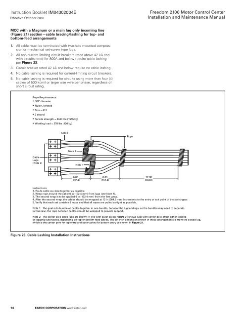
Figure 23. Cable Lashing <strong>Installation</strong> Instructions<br />
14<br />
Rope Requirements:<br />
3/8" diameter<br />
Nylon, twisted<br />
Size = #12<br />
3 str<strong>and</strong><br />
Tensile strength = 3340 lbs (1515 kg)<br />
Working load = 278 lbs (126 kg)<br />
Cable<br />
Lugs<br />
(Note 2)<br />
Cable<br />
Note 1<br />
Note 1<br />
6.00<br />
(152.4)<br />
eaton Corporation www.eaton.com<br />
6.00<br />
(152.4)<br />
Rope<br />
<strong>Freedom</strong> <strong>2100</strong> <strong>Motor</strong> <strong>Control</strong> <strong>Center</strong><br />
<strong>Installation</strong> <strong>and</strong> Maintenance Manual<br />
12.00<br />
(304.8)<br />
Instructions:<br />
1. Route cable as close together as possible.<br />
2. Wrap rope around the cable 6 in (152.4 mm) from lugs (see Note 1).<br />
3. The second wrap is to be applied 6 in (152.4 mm) from the first wrap.<br />
4. After the second wrap, the cables should be wrapped at 12 in (304.8 mm) increments to the entry or exit point of the switchgear.<br />
5. Verify that each set contains 5 loops <strong>and</strong> that all ropes are pulled as tight as possible.<br />
Note 1: The goal is to bundle all cables together in one bundle, but near the lug l<strong>and</strong>ings, so the bundles may need to separate.<br />
In this case, the rope between cables should be wrapped to provide support.<br />
Note 2: The center pole cable lugs are shown in-line with outer poles; Figure 21 shows lugs with center pole offset either leading<br />
or lagging outer poles, depending on top or bottom feed cables. The six-inch dimension shown in these arrangements is from the closed lug,<br />
which is the center pole for top entry <strong>and</strong> outer poles for bottom entry as shown in Figure 21.


