

Freedom 2100 Motor Control Center Installation and - Eaton Canada
Freedom 2100 Motor Control Center Installation and - Eaton Canada
Freedom 2100 Motor Control Center Installation and - Eaton Canada

You also want an ePaper? Increase the reach of your titles
YUMPU automatically turns print PDFs into web optimized ePapers that Google loves.
Instruction Booklet IM04302004E<br />
Effective October 2010<br />
part 1. General information<br />
The <strong>Motor</strong> <strong>Control</strong> <strong>Center</strong><br />
The <strong>Eaton</strong> <strong>Freedom</strong> <strong>2100</strong> <strong>Motor</strong> <strong>Control</strong> <strong>Center</strong> may be joined to<br />
existing Five Star, Series <strong>2100</strong>, <strong>and</strong> Advantage installations using<br />
the splice bar kits common to both . Units designed for the <strong>Freedom</strong><br />
<strong>2100</strong> can be mounted in Five Star Series <strong>and</strong> Series <strong>2100</strong> sections,<br />
but the opposite is not recommended, because Five Star <strong>and</strong> Series<br />
<strong>2100</strong> units may lack terminal blocks <strong>and</strong> sufficient interrupting capacity<br />
. The <strong>Freedom</strong> <strong>2100</strong> MCC may be joined to existing <strong>Eaton</strong> <strong>Freedom</strong><br />
Unitrol <strong>and</strong> F10 Unitrol MCC’s with a special splice bar kit, but units<br />
are not interchangable<br />
<strong>Control</strong> <strong>Center</strong> Nomenclature<br />
The numbers shown in parentheses in the following text refer to the<br />
balloon legends in Figure 2 .<br />
The <strong>Eaton</strong> <strong>Freedom</strong> <strong>2100</strong> <strong>Motor</strong> <strong>Control</strong> <strong>Center</strong> consists of one or<br />
more totally enclosed, dead front, free st<strong>and</strong>ing structural assemblies<br />
90 inches high which are compartmentalized to house individual<br />
control units . (2) With control units mounted in the front side only,<br />
the structure may be 16 or 21 inches deep . For mounting units backto-back,<br />
the structure is 21 inches deep . Steel covers (7) enclose<br />
the structure at the top, sides <strong>and</strong> at the rear of front-mounted-only<br />
structures .<br />
A vertical bus system installed in each vertical section is connected<br />
to the horizontal bus to feed the individual control units . The vertical<br />
bus is isolated by a full height barrier . (6) An optional labyrinth barrier<br />
provides both isolation <strong>and</strong> insulation . An automatic shutter is<br />
included with the labyrinth barrier system to cover the stab openings<br />
for each control unit .<br />
At the top of each section, a door provides ready access to the top<br />
horizontal wireway (11) <strong>and</strong> ground bus . The horizontal wireway<br />
is isolated from the bus systems by steel barriers which can be<br />
removed for installation <strong>and</strong> maintenance operations . Adequate<br />
space is provided for control wiring <strong>and</strong> top cable entry .<br />
At the bottom of each section, a door (18) provides ready access to<br />
the bottom horizontal wireway, <strong>and</strong> neutral bus (if provided) . The<br />
bottom of each section is completely open to provide unrestricted<br />
bottom entry of cable <strong>and</strong> conduit .Channel sills may be installed<br />
across the bottom of the control center if specified, <strong>and</strong> an optional<br />
bottom plate may also be specified .<br />
A vertical wireway 8 inches deep, extending the full 90 inch height of<br />
the control center is located to the right of each unit compartment .<br />
This wireway is covered by two hinged doors (15) <strong>and</strong> contains cable<br />
supports to secure wire bundle s<strong>and</strong> cables . The vertical wireway<br />
joins the horizontal wireway at the top <strong>and</strong> bottom to provide unobstructed<br />
space for interwiring .<br />
Each vertical section provides space to mount up to six controller<br />
units (2) with a minimum height of 12 inches, in increments of six<br />
inches, for a total of 72 inches of usable space . <strong>Control</strong>lers through<br />
NEMA Size 5 are drawout type (except reduced-voltage starters) .<br />
These drawout unit assemblies are a completely self-contained package<br />
consisting of a steel enclosure, operating h<strong>and</strong>le <strong>and</strong> electrical<br />
components . The drawout assembly slides into this compartment<br />
on guide rails (11) to provide easy withdrawal <strong>and</strong> reinsertion <strong>and</strong><br />
to ensure precise alignment of the unit stabs with the vertical bus .<br />
Each drawout unit is held in place by a single quarter-turn latch (4)<br />
which can only been gaged when the unit stabs are fully mated with<br />
the vertical bus . Each unit has a separate door, (1)held closed by a<br />
minimum of two quarter-turn fasteners .<br />
2<br />
eaton Corporation www.eaton.com<br />
<strong>Freedom</strong> <strong>2100</strong> <strong>Motor</strong> <strong>Control</strong> <strong>Center</strong><br />
<strong>Installation</strong> <strong>and</strong> Maintenance Manual<br />
The operating h<strong>and</strong>le on the controller unit (3) moves vertically . In<br />
the ON or TRIPPED positions,the h<strong>and</strong>le interlocks with the unit<br />
door to prevent its opening . In this position, authorized personnel<br />
can open the door by turning the defeater mechanism screw . (21)<br />
With the unit door open <strong>and</strong> the operating h<strong>and</strong>le in the ON position,<br />
another interlock to the divider pan prevents removal of the unit .<br />
This same interlock prevents insertion of the unit unless the h<strong>and</strong>le<br />
mechanism is in the OFF position . To ensure that units are not energized<br />
accidentally or by unauthorized personnel, the h<strong>and</strong>le mechanism<br />
can be padlocked in the OFF position . Space for a minimum<br />
of three padlocks is provided on each h<strong>and</strong>le . The device panel (5)<br />
is mounted on the drawout unit . It will accommodate up to six pilot<br />
devices . The overload reset button is mounted on the unit door .<br />
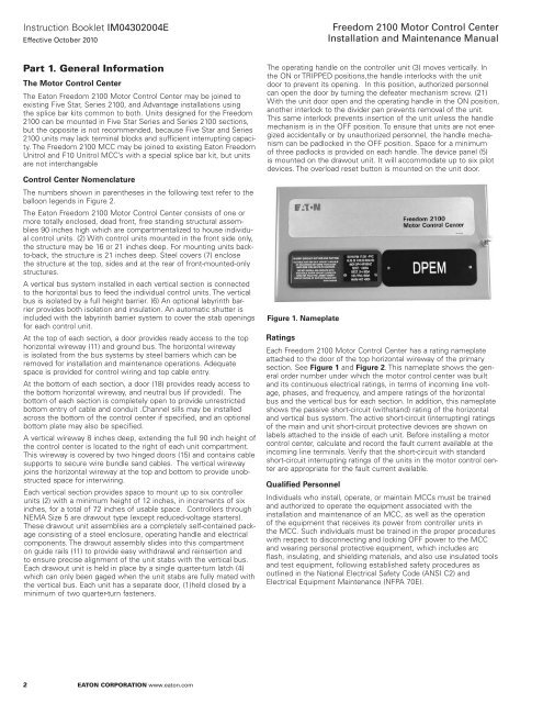
Figure 1. Nameplate<br />
Ratings<br />
Each <strong>Freedom</strong> <strong>2100</strong> <strong>Motor</strong> <strong>Control</strong> <strong>Center</strong> has a rating nameplate<br />
attached to the door of the top horizontal wireway of the primary<br />
section . See Figure 1 <strong>and</strong> Figure 2 . This nameplate shows the general<br />
order number under which the motor control center was built<br />
<strong>and</strong> its continuous electrical ratings, in terms of incoming line voltage,<br />
phases, <strong>and</strong> frequency, <strong>and</strong> ampere ratings of the horizontal<br />
bus <strong>and</strong> the vertical bus for each section . In addition, this nameplate<br />
shows the passive short-circuit (withst<strong>and</strong>) rating of the horizontal<br />
<strong>and</strong> vertical bus system . The active short-circuit (interrupting) ratings<br />
of the main <strong>and</strong> unit short-circuit protective devices are shown on<br />
labels attached to the inside of each unit . Before installing a motor<br />
control center, calculate <strong>and</strong> record the fault current available at the<br />
incoming line terminals . Verify that the short-circuit with st<strong>and</strong>ard<br />
short-circuit interrupting ratings of the units in the motor control center<br />
are appropriate for the fault current available .<br />
Qualified Personnel<br />
Individuals who install, operate, or maintain MCCs must be trained<br />
<strong>and</strong> authorized to operate the equipment associated with the<br />
installation <strong>and</strong> maintenance of an MCC, as well as the operation<br />
of the equipment that receives its power from controller units in<br />
the MCC . Such individuals must be trained in the proper procedures<br />
with respect to disconnecting <strong>and</strong> locking OFF power to the MCC<br />
<strong>and</strong> wearing personal protective equipment, which includes arc<br />
flash, insulating, <strong>and</strong> shielding materials, <strong>and</strong> also use insulated tools<br />
<strong>and</strong> test equipment, following established safety procedures as<br />
outlined in the National Electrical Safety Code (ANSI C2) <strong>and</strong><br />
Electrical Equipment Maintenance (NFPA 70E) .


