

Freedom 2100 Motor Control Center Installation and - Eaton Canada
Freedom 2100 Motor Control Center Installation and - Eaton Canada
Freedom 2100 Motor Control Center Installation and - Eaton Canada

Create successful ePaper yourself
Turn your PDF publications into a flip-book with our unique Google optimized e-Paper software.
Instruction Booklet IM04302004E<br />
Effective October 2010<br />
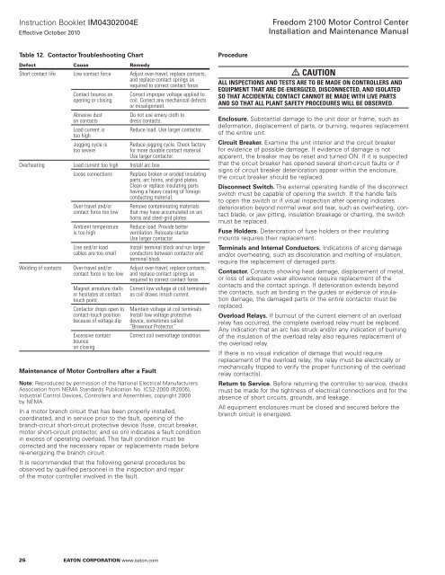
Table 12. Contactor Troubleshooting Chart<br />
Defect Cause remedy<br />
Short contact life Low contact force Adjust over-travel, replace contacts,<br />
<strong>and</strong> replace contact springs as<br />
required to correct contact force.<br />
26<br />
Contact bounce on<br />
opening or closing<br />
Abrasive dust<br />
on contacts<br />
Load current is<br />
too high<br />
Jogging cycle is<br />
too severe<br />
eaton Corporation www.eaton.com<br />
Correct improper voltage applied to<br />
coil. Correct any mechanical defects<br />
or misalignment.<br />
Do not use emery cloth to<br />
dress contacts.<br />
Reduce load. Use larger contactor.<br />
Reduce jogging cycle. Check factory<br />
for more durable contact material.<br />
Use larger contactor.<br />
Overheating Load current too high Install arc box.<br />
Loose connections Replace broken or eroded insulating<br />
parts, arc horns, <strong>and</strong> grid plates.<br />
Clean or replace insulating parts<br />
having a heavy coating of foreign<br />
conducting material.<br />
Over-travel <strong>and</strong>/or<br />
contact force too low<br />
Ambient temperature<br />
is too high<br />
Line <strong>and</strong>/or load<br />
cables are too small<br />
Welding of contacts Over-travel <strong>and</strong>/or<br />
contact force is too low<br />
Magnet armature stalls<br />
or hesitates at contact<br />
touch point<br />
Contactor drops open to<br />
contact-touch position<br />
because of voltage dip<br />
Excessive contact<br />
bounce<br />
on closing<br />
Maintenance of <strong>Motor</strong> <strong>Control</strong>lers after a Fault<br />
Remove contaminating materials<br />
that may have accumulated on arc<br />
horns <strong>and</strong> steel-grid plates.<br />
Reduce load. Provide better<br />
ventilation. Relocate starter.<br />
Use larger contactor.<br />
Install terminal block <strong>and</strong> run larger<br />
conductors between contactor <strong>and</strong><br />
terminal block.<br />
Adjust over-travel, replace contacts,<br />
<strong>and</strong> replace contact springs as<br />
required to correct contact force.<br />
Correct low voltage at coil terminals<br />
as coil draws inrush current.<br />
Maintain voltage at coil terminals.<br />
Install low voltage protective<br />
device, sometimes called<br />
“Brownout Protector.”<br />
Correct coil overvoltage condition.<br />
Notee: Reproduced by permission of the National Electrical Manufacturers<br />
Association from NEMA St<strong>and</strong>ards Publication No . ICS2-2000 (R2005),<br />
Industrial <strong>Control</strong> Devices, <strong>Control</strong>lers <strong>and</strong> Assemblies, copyright 2000<br />
by NEMA .<br />
In a motor branch circuit that has been properly installed,<br />
coordinated, <strong>and</strong> in service prior to the fault, opening of the<br />
branch-circuit short-circuit protective device (fuse, circuit breaker,<br />
motor short-circuit protector, <strong>and</strong> so on) indicates a fault condition<br />
in excess of operating overload . This fault condition must be<br />
corrected <strong>and</strong> the necessary repair or replacements made before<br />
re-energizing the branch circuit .<br />
It is recommended that the following general procedures be<br />
observed by qualified personnel in the inspection <strong>and</strong> repair<br />
of the motor controller involved in the fault .<br />
Procedure<br />
<strong>Freedom</strong> <strong>2100</strong> <strong>Motor</strong> <strong>Control</strong> <strong>Center</strong><br />
<strong>Installation</strong> <strong>and</strong> Maintenance Manual<br />
Caution<br />
all inSpeCtionS <strong>and</strong> teStS are to be Made on <strong>Control</strong>lerS <strong>and</strong><br />
equipMent tHat are de-energized, diSConneCted, <strong>and</strong> iSolated<br />
So tHat aCCidental ContaCt Cannot be Made witH live partS<br />
<strong>and</strong> So tHat all plant Safety proCedureS will be obServed.<br />
Enclosure. Substantial damage to the unit door or frame, such as<br />
deformation, displacement of parts, or burning, requires replacement<br />
of the entire unit .<br />
Circuit Breaker. Examine the unit interior <strong>and</strong> the circuit breaker<br />
for evidence of possible damage . If evidence of damage is not<br />
apparent, the breaker may be reset <strong>and</strong> turned ON . If it is suspected<br />
that the circuit breaker has opened several short-circuit faults or if<br />
signs of circuit breaker deterioration appear within the enclosure,<br />
the circuit breaker should be replaced .<br />
Disconnect Switch. The external operating h<strong>and</strong>le of the disconnect<br />
switch must be capable of opening the switch . If the h<strong>and</strong>le fails<br />
to open the switch or if visual inspection after opening indicates<br />
deterioration beyond normal wear <strong>and</strong> tear, such as overheating, contact<br />
blade, or jaw pitting, insulation breakage or charring, the switch<br />
must be replaced .<br />
Fuse Holders. Deterioration of fuse holders or their insulating<br />
mounts requires their replacement .<br />
Terminals <strong>and</strong> Internal Conductors. Indications of arcing damage<br />
<strong>and</strong>/or overheating, such as discoloration <strong>and</strong> melting of insulation,<br />
require the replacement of damaged parts .<br />
Contactor. Contacts showing heat damage, displacement of metal,<br />
or loss of adequate wear allowance require replacement of the<br />
contacts <strong>and</strong> the contact springs . If deterioration extends beyond<br />
the contacts, such as binding in the guides or evidence of insulation<br />
damage, the damaged parts or the entire contactor must be<br />
replaced .<br />
Overload Relays. If burnout of the current element of an overload<br />
relay has occurred, the complete overload relay must be replaced .<br />
Any indication that an arc has struck <strong>and</strong>/or any indication of burning<br />
of the insulation of the overload relay also requires replacement of<br />
the overload relay .<br />
If there is no visual indication of damage that would require<br />
replacement of the overload relay, the relay must be electrically or<br />
mechanically tripped to verify the proper functioning of the overload<br />
relay contact(s) .<br />
Return to Service. Before returning the controller to service, checks<br />
must be made for the tightness of electrical connections <strong>and</strong> for the<br />
absence of short circuits, grounds, <strong>and</strong> leakage .<br />
All equipment enclosures must be closed <strong>and</strong> secured before the<br />
branch circuit is energized .


