

Freedom 2100 Motor Control Center Installation and - Eaton Canada
Freedom 2100 Motor Control Center Installation and - Eaton Canada
Freedom 2100 Motor Control Center Installation and - Eaton Canada

You also want an ePaper? Increase the reach of your titles
YUMPU automatically turns print PDFs into web optimized ePapers that Google loves.
Instruction Booklet IM04302004E<br />
Effective October 2010<br />
part 9. Unit installation <strong>and</strong> adjustment<br />
Door Removal <strong>and</strong> <strong>Installation</strong><br />
All doors on the control center are mounted on pin hinges<br />
to facilitate removal for installation <strong>and</strong> maintenance operations.<br />
With the operating h<strong>and</strong>le on the OFF position, rotate<br />
the quarter-turn latches, open the door, remove the hinge<br />
pins as shown in Figure 28, partially close the door <strong>and</strong> lift it<br />
from the structure. Reverse this procedure for installation.<br />
Unit Removal <strong>and</strong> <strong>Installation</strong><br />
After opening <strong>and</strong>/or removing the unit door, the control unit is<br />
exposed . With a screwdriver, push in on the latch at the top center<br />
of the unit <strong>and</strong> rotate ¼turn counterclockwise .<br />
Caution<br />
unitS 18” or More HigH Have a retaining braCe at tHe lower edge<br />
of eaCH Side of tHe unit fraMe to add Stability in SHipping. tHe<br />
SHipping braCeS May be retained or reMoved after inStallation;<br />
unSCrew prior to unit witHdrawal.<br />
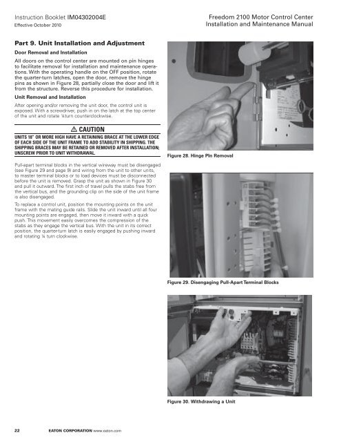
Pull-apart terminal blocks in the vertical wireway must be disengaged<br />
(see Figure 29 <strong>and</strong> page 9) <strong>and</strong> wiring from the unit to other units,<br />
to master terminal blocks or to load devices must be disconnected<br />
before the unit is removed . Grasp the unit as shown in Figure 30<br />
<strong>and</strong> pull it outward . The first inch of travel pulls the stabs free from<br />
the vertical bus, <strong>and</strong> the grounding clip on the side of the unit frame<br />
is also disengaged .<br />
To replace a control unit, position the mounting points on the unit<br />
frame with the mating guide rails . Slide the unit inward until all four<br />
mounting points are engaged, then move it inward with a quick<br />
push . This movement easily overcomes the compression of the<br />
stabs as they engage the vertical bus . With the unit in its correct<br />
position, the quarter-turn latch is easily engaged by pushing inward<br />
<strong>and</strong> rotating ¼ turn clockwise .<br />
22<br />
eaton Corporation www.eaton.com<br />
Figure 28. Hinge PIn Removal<br />
<strong>Freedom</strong> <strong>2100</strong> <strong>Motor</strong> <strong>Control</strong> <strong>Center</strong><br />
<strong>Installation</strong> <strong>and</strong> Maintenance Manual<br />
Figure 29. Disengaging Pull-Apart Terminal Blocks<br />
Figure 30. Withdrawing a Unit


