You also want an ePaper? Increase the reach of your titles
YUMPU automatically turns print PDFs into web optimized ePapers that Google loves.
3<br />
128<br />
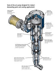
GRACO <strong>SEALANTS</strong> AND <strong>ADHESIVES</strong> EQUIPMENT ❚ METERING PACKAGES<br />
PrecisionFlo XL<br />
Sealant & Adhesive Dispensing System<br />
All Precision FloXL Systems are ordered using the PrecisionFlo XL<br />
Configurated Order Form. Select components using the instructions<br />
below and enter your choice on the order form.<br />
Code A Configuration<br />
Option 1 PrecisionFlo XL Module: Choose Option 1 when configuring<br />
a complete module, which includes a control<br />
panel and fluid control equipment. Feed pumps are<br />
not included, and must be ordered separately.<br />
Option 2 Electrical Enclosure only: Choose Option 2 to order an<br />
electrical enclosure only. You will receive only an electrical<br />
enclosure; you will supply the fluid control components.<br />
But make the rest of the choices on the configurator<br />
as if you were ordering a complete module.<br />
The electrical enclosure will be configured to control<br />
the components that you select and be loaded with<br />
the proper software at the factory.<br />
Code B Enclosure<br />
Option N Back Plane Only: Choose Option N when the<br />
PrecisionFlo XL controls will be integrated into a user<br />
specified enclosure, for example a control panel for a<br />
robot. The back plane will be factory tested and<br />
loaded with software. The back plane will include a<br />
pre-wired cable receptacle plate for testing. This plate<br />
can be used if applicable, or replaced by the user if<br />
required. The User Interface selected in Code D will be<br />
shipped separate for integration into the user specified<br />
enclosure, along with the key switch for interface operation.<br />
Option 1 Rotary Switch Disconnect: Choose Option 1 to order an<br />
electrical enclosure with a rotary power disconnect<br />
switch. The electrical enclosure is CE marked.<br />
Option 2 Knife Switch Disconnect: Choose Option 2 to order an<br />
electrical enclosure with a knife switch power disconnect.<br />
The electrical enclosure is CE marked.<br />
Code C Cables<br />
Option 1 All cables included: choose Option 1 to receive the<br />
cable set appropriate for the configured system.<br />
Operations Cable, PrecisionFlo XL Enclosure to Fluid<br />
Plate, 60 ft. (18.3 m).<br />
Motor Cable, PrecisionFlo XL Enclosure to Fluid Plater,<br />
60 ft. (18.3 m) (supplied when PrecisionFlo Linear<br />
Motor option is chosen in Code H).<br />
PrecisionSwirl Cable, 55 ft. (16.8 m) (supplied when<br />
the PrecisionSwirl and orbiter extension cable options<br />
are chosen in Coades LA and LB). See Code LB for<br />
cable choices.<br />
Analog Robot I/O Cable, PrecisionFlo XL Enclosure to<br />
Robot Enclosure, 40 ft. (12.2 m) (supplied when 24<br />
VDC or 120 VAC interface option is chosen in Code F).<br />
Digital Robot I/O Cable, PrecisionFlo XL Enclosure to<br />
Robot Enclosure, 40 ft. (12.2 m) (supplied when 24<br />
VDC or 120 VAC interface option is chosen in Code F).<br />
Option 2 No cables included: Choose Option 2 to receive no<br />
cables. This option should be selected if a different<br />
length cable is required by the specific installation.<br />
Cables can be ordered separately from Graco. See the<br />
PrecisionFlo XL Manual 309364 for cable construction<br />
guidelines and mating connector information.<br />
Code D User Interface<br />
Option 1 Easy Key User Interface: Choose Option 1 to receive<br />
the easy key user interface. The easy key user interface<br />
is a monochrome, backlit display with a membrane<br />
keypad. The display is capable of controlling all of the<br />
standard PrecisionFlo XL features.<br />
Option 2 Touch Screen User Interface: Choose Option 2 to<br />
receive the touch screen user interface. The touch<br />
screen user interface incorporates a color touch screen.<br />
The display has all of the same features as the touch<br />
screen controller, plus I/O monitoring, a real-time oscilloscope<br />
for valve timing, additional data and fault logging<br />
capabilities, and more.<br />
Option 3 Remote Mount Advanced User Interface: Choose<br />
Option 3 to receive the touch screen user interface in a<br />
remote mounted enclosure. This option is used when<br />
the mounting area for the controller is limited.<br />
Code E Primary Voltage<br />
Option 1 110-120 VAC: Choose Option 1 when 110-120 VAC is<br />
available for control power. Acceptable power supply<br />
range is 85-164 VAC, 50 to 60 Hz, single phase. Do<br />
not choose this option if selecting temperature conditioning<br />
or electric heat in code G.<br />
Option 2 220-240 VAC: Choose Option 2 when 220-240 VAC is<br />
available for control power. Acceptable power supply<br />
range is 200-240 VAC, 50 to 60 Hz, single phase. The<br />
enclosure will come with an internal transformer prewired<br />
for this primary voltage.<br />
Option 3 400-480 VAC: Choose Option 3 when 400-480 VAC is<br />
available for control power. Acceptable power supply<br />
range is 400-480 VAC, 50 to 60 Hz, single phase. The<br />
enclosure will come with an internal transformer prewired<br />
for this primary voltage