Software manual for use with color sensors of the Series - Silicann
Software manual for use with color sensors of the Series - Silicann
Software manual for use with color sensors of the Series - Silicann

Create successful ePaper yourself
Turn your PDF publications into a flip-book with our unique Google optimized e-Paper software.
User Manual<br />
PCS Sensor <strong>S<strong>of</strong>tware</strong><br />
Table 4: Output <strong>for</strong>mats <strong>for</strong> <strong>color</strong> checking and classification<br />
Selection Description<br />
OFF The outputs keep <strong>the</strong>ir last result and are switched <strong>of</strong>f.<br />
ONE HOT This is a “1-out-<strong>of</strong>-N” encoding. Each <strong>color</strong> value in <strong>the</strong> internal <strong>color</strong><br />
table (please refer to sect. 1.2.3, subsect. “COLOR TABLE”) is directly<br />
assigned to one output signal. Thus <strong>the</strong>re are as many <strong>color</strong>s possible as<br />
sensor outputs are available.<br />
ONE HOT INV. Refer to “ONE HOT“, but output signals are inverted<br />
BINARY The result is encoded binary and thus 2 n (n = number <strong>of</strong> sensor outputs)<br />
states are possible. The index 255 is <strong>use</strong>d as “Not recognized” or “Out<br />
<strong>of</strong> tolerance” in <strong>the</strong> CHECK mode.<br />
BINARY INV. Refer to “BINARY“, but output signals are inverted<br />
DEVIATION 4 If no matching <strong>color</strong> can be found, this result <strong>for</strong>mat indicates <strong>the</strong> <strong>color</strong>deviation<br />
from <strong>the</strong> first entry <strong>of</strong> <strong>the</strong> <strong>color</strong>-table. The meaning <strong>of</strong> <strong>the</strong><br />
different output ports is shown in Table 5.<br />
This mode is only available <strong>with</strong> <strong>the</strong> <strong>color</strong>-space-modes L*a*b* or<br />
LAB99 and processing mode CHECK CYL.<br />
Table 5: Deviation-mode signal assignment<br />
Ausgang Anzeigensegment<br />
OUT0 1 = <strong>color</strong> detected, 0 = No <strong>color</strong> detected<br />
OUT1 Darker<br />
OUT2 Brighter<br />
OUT3 Deviation to red<br />
OUT4 Deviation to green<br />
OUT5 Deviation to yellow<br />
OUT6 Deviation to blue<br />
OUT7 Not <strong>use</strong>d<br />
RUNNING MODE<br />
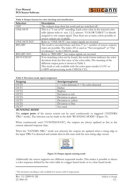
The output ports <strong>of</strong> <strong>the</strong> sensor system can be <strong>use</strong>d continuously or triggered (“EXTERN<br />
TRG.“ mode). The selection can be made in <strong>the</strong> field “RUNNING MODE“ (Figure 13).<br />
When continuously <strong>use</strong>d (“CONTINOUOS”), <strong>the</strong> outputs are always updated as fast as <strong>the</strong><br />
current adjusted response time.<br />
When <strong>the</strong> “EXTERN TRG.“ mode was selected, <strong>the</strong> outputs are updated when a rising edge at<br />
<strong>the</strong> input TRG 0 is detected and remain <strong>the</strong>n in this state until <strong>the</strong> next rising edge occurs.<br />
Figure 13: Output signals running mode<br />
Additionally <strong>the</strong> sensor supports two different sequential modes. This makes it possible to detect<br />
a <strong>color</strong> sequence defined by <strong>the</strong> <strong>color</strong> table in a trigger based mode or in a time based mode.<br />
4 The deviation encoding is only available <strong>for</strong> <strong>sensors</strong> <strong>with</strong> 8 output ports.<br />
Rev. 5.1 (2009-01-28) Subject to change<br />
22-3061-01 - 12 -