175A - HP Archive
175A - HP Archive
175A - HP Archive

Create successful ePaper yourself
Turn your PDF publications into a flip-book with our unique Google optimized e-Paper software.
Section III Model <strong>175A</strong><br />
Figure 3-1<br />
p OCCURRENCE<br />
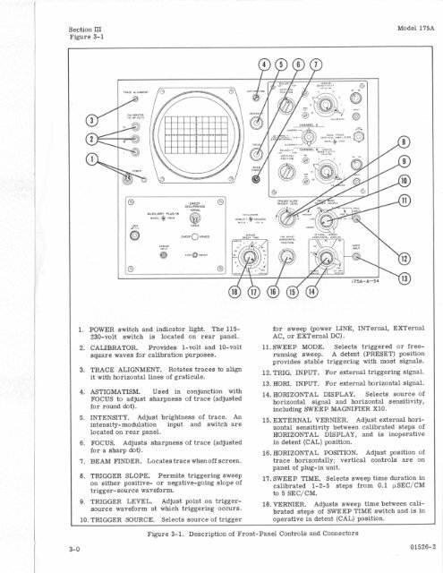
1. POWER switch and indicator light. The 115- for sweep (power LINE, INTernal, EXTernal<br />
230-volt switch is located on rear panel. AC, or EXTernal DC).<br />
2. CALIBRATOR, Provides 1-volt and 10-volt<br />
square waves for calibration purposes.<br />
11. SWEEP MODE.<br />
running sweep.<br />
Selects triggered or free-<br />
A detent (PRESET) position<br />
provides stable triggering with most signals.<br />
3. TRACE ALIGNMENT. Rotates traces to align<br />
it with horizontal lines of graticule.<br />
12. TRIG. INPUT. For external triggering signal.<br />
13. HORI. INPUT. For external horizontal signal.<br />
4. ASTIGMATISM. Used in conjunction with<br />
FOCUS to adjust sharpness of trace (adjusted<br />
for round dot).<br />
14. HORIZONTAL DISPLAY. Selects source of<br />
horizontal signal and horizontal sensitivity,<br />
including SWEEP MAGNIFIER X10.<br />
5. INTENSITY. Adjust brightness of trace. An<br />
intensity-modulation input and switch are<br />
located on rear panel.<br />
15. EXTERNAL VERNIER. Adjust external horizontal<br />
sensitivity between calibrated steps of<br />
HORIZONTAL DISPLAY, and is inoperative<br />
6. FOCUS. Adjusts sharpness of trace (adjusted in detent (CAL) position.<br />
for a sharp dot).<br />
16. HORIZONTAL POSITION. Adjust position of<br />
7. BEAM FINDER. Locates trace whenoff screen. trace horizontally; vertical controls are on<br />
panel of plug-in unit.<br />
8. TRIGGER SLOPE. Permits triggering sweep<br />
on either positive- or negative-going slope of<br />
trigger-source waveform.<br />
17. SWEEP TIME. Selects sweep time duration in<br />
calibrated 1-2-5 steps from 0.1 pSEC/CM<br />
to 5 SEC/CM.<br />
9. TRIGGER LEVEL. Adjust point on triggersource<br />
waveform at which triggering occurs.<br />
18. VERNIER. Adjusts sweep time between calibrated<br />
stem of SWEEP TIME switch and is in<br />
10. TRIGGER SOURCE. Selects source of trigger operative in detent (CAL) position.<br />
Figure 3-1. Description of Front-Panel Controls and Connectors<br />
3-0 01526-2<br />
/<br />
0<br />
0