175A - HP Archive
175A - HP Archive
175A - HP Archive

Create successful ePaper yourself
Turn your PDF publications into a flip-book with our unique Google optimized e-Paper software.
Section V<br />
Figures 5-29 and 5-30<br />
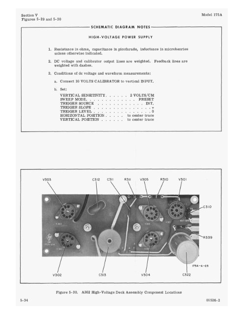
SCHEMATIC DIAGRAM NOTES<br />
HIGH-VOLTAGE POWER SUPPLY<br />
1. Resistance in ohms, capacitance in picofarads, inductance in microhenries<br />
unless otherwise indicated.<br />
2. DC voltage and calibrator output lines are weighted. Feedback lines are<br />
weighted with dashes.<br />
3. Conditions of dc voltage and waveform measurements:<br />
a. Connect 10 VOLTS CALIBRATOR to vertical INPUT.<br />
b. Set:<br />
VERTICAL SENSITIVITY. ..... 2 VOLTS/CM<br />
SWEEP MODE. ............ PRESET<br />
TRIGGER SOURCE ............ INT.<br />
TRIGGER SLOPE ............... +<br />
TRIGGER LEVEL. .............. 0<br />
HORIZONTAL POSITION. .... to center trace<br />
VERTICAL POStTION ..... to center trace<br />
V303 C312 c311 R311 V305 R310 V301<br />
I<br />
V302<br />
I I<br />
C313<br />
V304<br />
Figure 5-30. A302 High-Voltage Deck Assembly Component Locations<br />
I<br />
C322<br />
Model <strong>175A</strong><br />
C310<br />
<strong>175A</strong> -A -23<br />
5-34 01526-2