175A - HP Archive
175A - HP Archive
175A - HP Archive

Create successful ePaper yourself
Turn your PDF publications into a flip-book with our unique Google optimized e-Paper software.
Section IV<br />
Paragraphs 4-34 to 4-41<br />
INPUT<br />
A. CIRCUIT<br />
m<br />
OUTPUT<br />
B. COMPOSITE CURVE LO - M - 643<br />
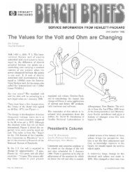
Figure 4-5. Trigger Generator Simplified Circuit<br />
and Composite Characteristic<br />
change in voltage at the input to integratorV106 dur-<br />
ing the sweep time is only about one volt. Voltage<br />
across the sweep resistor, then, changes by about<br />
1%, and the current through the resistor changes by<br />
the same amount. The current through the sweep<br />
resistor is the charging current for the sweep capaci-<br />
tor; therefore, the voltage across the sweep capacitor<br />
changes quite linearly with time, and the sweep sig-<br />
nal is a nearly linear voltage ramp. The SWEEP<br />
TIME switch changes the value of sweep resistor or<br />
capacitor to change the sweep time. The sweep out-<br />
put is applied to the horizontal amplifier through the<br />
horizontal plug-in.<br />
4-34. An attenuated sweep signal is applied to the<br />
input of gate generator V103/V104A through hold-off<br />
cathode follower V105B and section B of bias control<br />
cathode follower V109. This signal drives the input<br />
of the gate generator up to the upper hysteresis limit<br />
and causes the gate generator to switch back to its<br />
pre-sweep state. The gate generator then ends the<br />
the gates, blanking the crt and forward biasing switch<br />
4-4<br />
I<br />
V<br />
Model <strong>175A</strong><br />
diode CR106. The switch diode returns the input of<br />
integrator V106 to its pre-sweep level, discharging<br />
the sweep capacitor.<br />
4-35. During a sweep time, hold-off cathode follower<br />
V105B charges a hold-off capacitor. After the sweep<br />
ends, this capacitor lets the input to gate generator<br />
V103/V104A down slowly enough to prevent that cir-<br />
cuit from being triggered again until the remaining<br />
sweep circuits have recovered completely. The<br />
SWEEP TIME switch changes the size of the hold-off<br />
capacitor with sweep time.<br />
4-36. Clamp V104B ensures that each sweep starts<br />
from the same voltage level, about -50 volts.<br />
4-37. The SWEEP MODE control R172 (figure 5-22)<br />
determines the no-signal bias at the input to gate gen-<br />
erator V103/V104A by setting the bias on the A sec-<br />
tion of bias control cathode follower V109. With the<br />
control set to PRESET or in the TRIGGER portion of<br />
its adjustable range, the gate generator bias cannot<br />
drop below its lower hysteresis limit unless the trig-<br />
ger generator provides a trigger. With the control<br />
set in the FREE RUN portion of its adjustable range,<br />
the gate bias is allowed to drop below its lower hys-<br />
teresis limit. Thus as the hold-off capacitor dis-<br />
charges, it lets the gate generator bias all the way<br />
down to the lower hysteresis limit, and another sweep<br />
starts automatically.<br />
4- 38. SINGLE - SWE EP OPERATION.<br />
4-39. The SWEEP OCCURRENCE switch (on the panel<br />
of the horizontal plug-in unit) selects normal or<br />
single-sweep operation. Normal operation is dis-<br />
cussed above. For single-sweep operation, the<br />
SWEEP OCCURRENCE switch converts V109 into a<br />
Schmitt circuit. As the sweep signal from hold-off<br />
cathode follower V105B rises to end the gate from<br />
the gate generator, the sweep signal also switches<br />
the Schmitt circuit of V109 so that V109B conducts<br />
and V109A is cut off. The B section of V109 then<br />
holds the input to gate generator V103/V104A high<br />
enough so that triggers from the trigger generator<br />
cannot actuate the gate generator, and the sweep<br />
generating circuits are effectively disabled. A pos-<br />
itive signal applied to V109A switches the Schmitt<br />
circuit of V109 so that V109A conducts and V109B is<br />
cut off. The A section of V109 then sets the input to<br />
the gate generator according to the setting of the<br />
SWEEP MODE control, and the sweep generating cir-<br />
cuits are effectively armed. The switching signal<br />
for V109A can be an external signal applied to the<br />
ARMING INPUT connector or an internal signal ob-<br />
tained by switching SWEEP MODE control out of its<br />
PRESET position.<br />
4-40. SCHMITT TRIGGER CIRCUIT.<br />
4-41. The Schmitt trigger circuit is a form of bi-<br />
stable multivibrator used where fast-rising signals<br />
are required. Figure 4-6 shows a simplified Schmitt<br />
trigger circuit and input and output waveforms. If<br />
initially the input voltage is such that V1 is cut off,<br />
V2 conducts. As the input voltage becomes more pos-<br />
itive, it will eventually reach a predetermined level<br />
(a) at which the circuit changes state; V1 conducts<br />
01526-2