175A - HP Archive
175A - HP Archive
175A - HP Archive

Create successful ePaper yourself
Turn your PDF publications into a flip-book with our unique Google optimized e-Paper software.
Section 111 Model <strong>175A</strong><br />
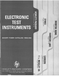
Figure 3-4<br />
@-<br />
UNDERCOMPENSATED<br />
CORRECTLY COMPENSATED<br />
OVERCOMPENSATED<br />
1. Set SWEEP TIME to 0.5 MSEC/MC. 7. Connect probe to vertical INPUT and touch<br />
tip to 10 VOLTS CALIBRATOR.<br />
2. SetHORIZONTAL DISPLAY to INT SWEEP XI.<br />
8. Ioosen knurled locknut behind rear flange of<br />
3. Set TRIGGER SOURCE to INT. test probe.<br />
4. Set SWEEP MODE to PRESET.<br />
9. Holding vinyl sheath behind locknut, rotate<br />
rear flange to obtain correctly compensated<br />
5. Set TRIGGER LEVEL to 0.<br />
square wave illustrated above.<br />
6. Set SENSITIVITY to 0.2 VOLTS/CM. 10. Tighten locknut without changing adjustment.<br />
Figure 3-4. Probe Compensation<br />
3-4 01526-2